Pd8 6 5 snoop e r modbus, 74 regist er, Data ty p e – Precision Digital PD865 User Manual
Page 74
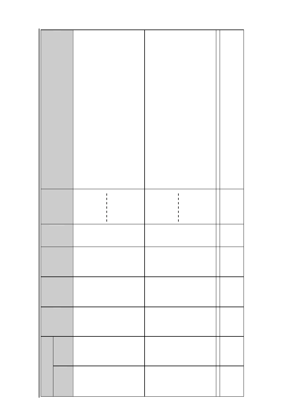
PD8
6
5
Snoop
e
r Modbus
Se
ria
l In
put Me
te
r
Ins
truc
tion M
a
nua
l: Re
gis
te
r Ta
ble
74
Regist
er
1
Name
A
c
c
ess
Limit
s
or
Range
2
Data
Ty
p
e
3
Func
tio
n
Code
(s)
Com
m
en
ts
Num
b
er
A
d
d
res
s
(hex
)
401
15
To
401
21
114 –
1
15
(0072 –
007
3)
116 –
1
17
(0074 –
007
5)
118
(007
6)
119
(007
7)
120
(007
8)
Set-point
Reset-point
Turn-on
dela
y
Turn-off
dela
y
Mode
Comm.
B
reak
R
ead
Wr
it
e
-1999
99 t
o
999
999
(S
e
t &
R
eset
)
0 t
o
19
9
0 t
o
19
9
B
it
s
4,
2, 1
,
0
Bits
6
,
5
Long
Long
Int
e
ger
Int
e
ger
Wo
rd
:
bits
03, 04, 16
03, 04,
06,1
6
Rela
y
3 parameter
s
.
Set and r
eset points
re
pres
ent
the displ
a
y
v
a
lue
w
ithout the
decima
l point.
See B
it
A
s
signment
Table 4
for operating
modes and bit
assignm
ent
s
.
401
22
To
401
28
121 –
1
22
(0079 –
007
A
)
123 –
1
24
(007B
–
007C
)
125
(007D
)
126
(007
E)
127
(007F)
Set-point
Reset-point
Turn-on
dela
y
Turn-off
dela
y
Mode
Comm.
B
reak
R
ead
Wr
it
e
-1999
99 t
o
999
999
(S
e
t &
R
eset
)
0 t
o
19
9
0 t
o
19
9
B
it
s
4,
2, 1
,
0
Bits
6
,
5
Long
Long
Int
e
ger
Int
e
ger
Wo
rd
:
bits
03, 04, 16
03, 04,
06,1
6
Rela
y
4 parameter
s
.
Set and r
eset points
re
pres
ent
the displ
a
y
v
a
lue
w
ithout the
decima
l point.
See B
it
A
s
signment
Table 4
for operating
modes and bit
assignm
ent
s
.
403
01
300
(012C
)
4-
20m
A
ou
t
– Mode
R
ead
Wr
it
e
Not
applicab
le
Int
e
ger:
bits
03, 04, 06,
16
Sele
ct
s out
put
opt
ion and
w
h
er
e t
h
e dat
a
s
ource f
o
r t
h
e 4-
20m
A
output. See Bit
A
ssig
n
ment Table
5.