Models, Multivideo models – Rose Electronics MultiVideo User Manual
Page 4
Advertising
MODELS
2
MULTIVIDEO INSTALLATION AND OPERATIONS MANUAL
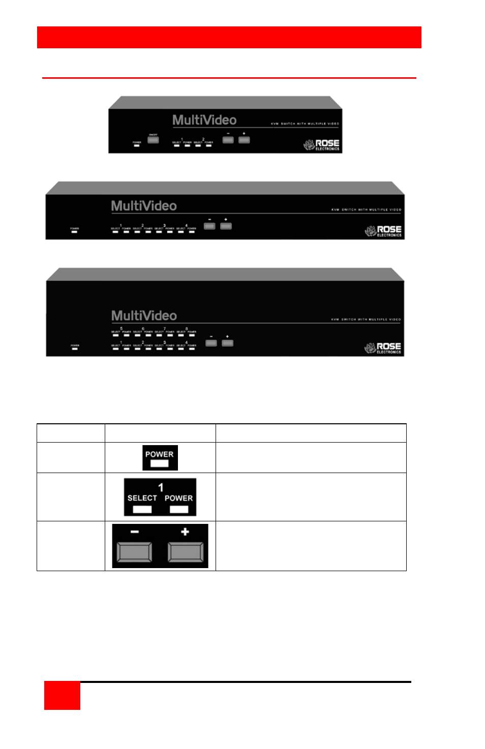
MultiVideo models
M – Chassis
B – Chassis
C - Chassis
Figure 1. MultiVideo models
Label
Description
Power
Power LED - Green when unit is on
LEDs
Indicator LEDs; Numbered pairs of
LEDs shows status and power of
connected computers
- and +
Switches*
- Connects to the previous CPU
+ Connects to the next CPU
* The - and + switches are used when:
upgrading the firmware
resetting the unit to factory defaults
running diagnostics.
Table 1. Front panel
Advertising