Installation guidelines, Cooling and ventilation, Mounting options – Rosen Aviation 1702 Series : 17.5 inch WideScreen High definition User Manual
Page 6
Rosen Aviation
17.5” HD Widescreen Display
Document Number: 102990
Revision: C
Date: 03/17/14
Template: 4.2.3-6-FM; Revision A; 16 May, 2005
Page 6 of 34
3. INSTALLATION GUIDELINES
3.1. Cooling and Ventilation
The 17.5” displays require free-air ventilation; do not block the top, bottom, or rear vent holes. A
minimum of ½-inch clearance is required for all vent holes. For bulkhead installations, ensure a
minimum of 1630 cubic inches around the display.
3.2. Mounting Options
You can mount
a 17.5” display from any of the four sides by removing the #10-32 screws, or use
a rear-surface mount using the threaded holes as mounting points.
Side mount
–left and right (six screws)
Rear-surface mount (minimum of four screws)
Top and bottom mount (eight screws)
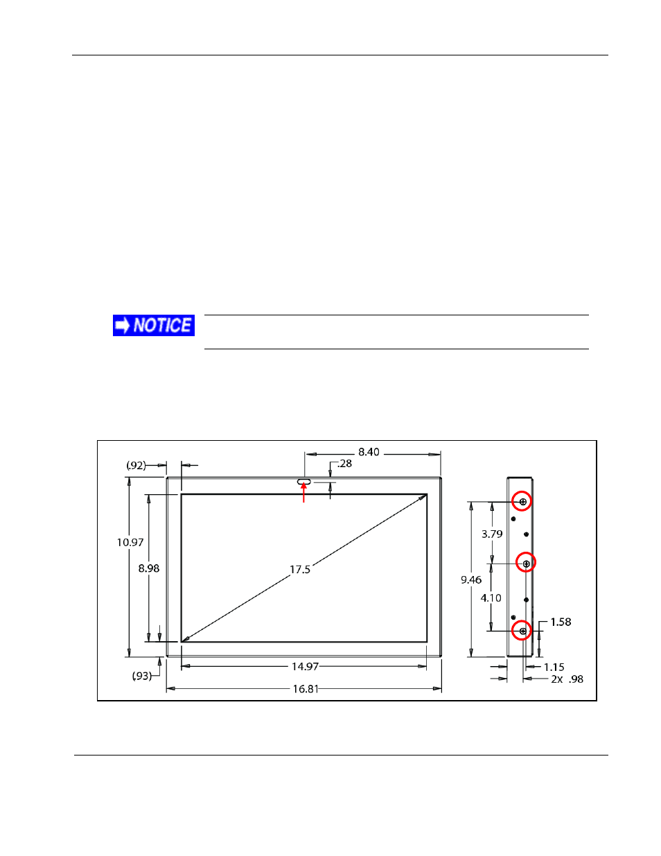
Drawings are available to assist in the installation process. Pay close attention to the dimensions
when considering installation requirements.
Touching the LCD with excessive force may leave pressure spots
that show in video display. Handle with care.
The display must be mounted with a minimum of four mounting screws. The following figures
show the mounting option dimensions for this display.
For mounting, remove only the #10-32 screws; do not remove the smaller #4-40 flathead screws.
Do not exceed a .375-inch insertion depth.
(Dimensions are in inches)
Figure 1 Dimensions for the side mounting holes
IR Receiver and
Status LED