Amprobe, Attention – Amprobe DMIII-Multitest Power-Quality-Recorder User Manual
Page 23
AMPROBE
DMIII MULTITEST
EN-21
6.2.
INSULATION TEST:
INSULATION RESISTANCE MEASUREMENT
The measurements comply with IEC 61557-2 and VDE 0413 part 1.
ATTENTION
Before performing an insulation test make sure that the circuit under test is
not energised and all the loads are disconnected.
Turn the rotary knob to the INSULATION TEST position.
The F1 key allows the operator to select one of the following measuring
modes:
MAN mode (Manual mode) Recommended test.
TMR mode (Timer mode: test duration depends on the selected interval
from 10 to 999 seconds). This test can be executed when the test
required a defined duration.
6.2.1. Measurement Procedure
1. Select the desired mode using the F1 key.
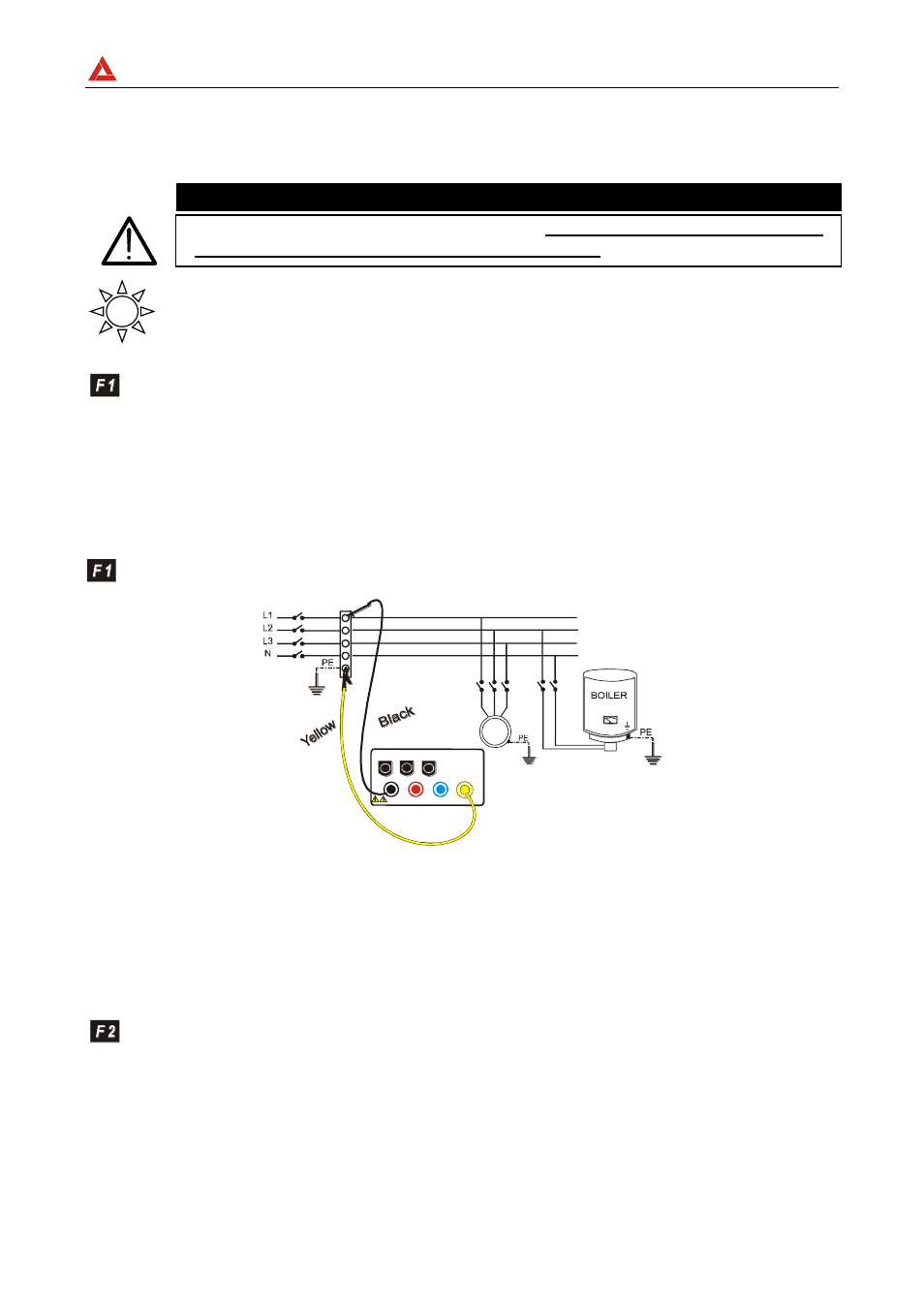
2. Connect the test leads to the instrument input terminals T1 and T4 respectively,
M
T1 T2 T3 T4
I1 I2 I3
(V1) (V2) (V3)
(COM)
Example: insulation measurement between phase and
earth in an electrical installation using untied cables.
3. If the cables supplied with the instrument are not long enough for the measurement
you can extend the black cable.
4. Connect the instrument terminals to the object that is to be submitted to the
insulation test after de-energizing the circuit under test and all the relative
loads (see previous picture).
5. By means of F2 select the test voltage suitable for the type of test to be
performed (see Table1). The values to be selected are:
50V (test on telecommunication system)
100V
250V
500V
1000V