Amprobe, Caution – Amprobe DMIII-Multitest Power-Quality-Recorder User Manual
Page 67
AMPROBE
DMIII MULTITEST
EN-65
8.3.
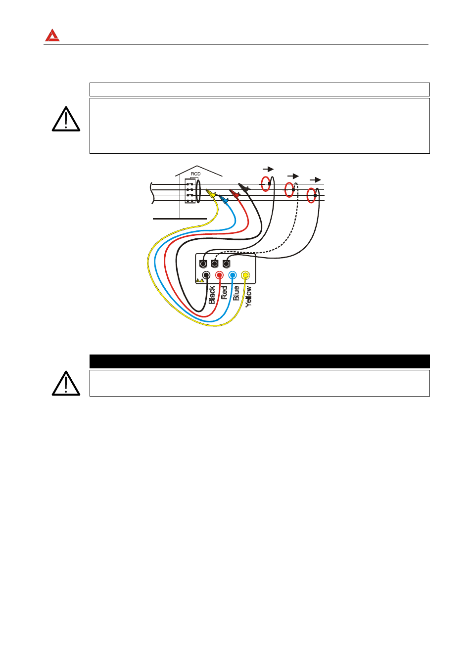
USING THE INSTRUMENT IN A THREE-PHASE 3-WIRE SYSTEM
CAUTION
The maximum voltage between V1, V2, V3 inputs is 600 V~ (CATII) /
350V~ phase to earth or 600V~ (CATIII) / 300 V~ phase to earth.
Do not measure voltages exceeding the limits prescribed by this manual.
Should you exceed the voltage limits you could damage the instrument
and/or its components or endanger your own safety.
L1
L2
L3
N
I1
I2
I3
T1 T2 T3 T4
I1 I2 I3
(V1) (V2) (V3)
(COM)
Instrument connection in a three-phase 3-wire system
CAUTION
Please note that in this case the Yellow cable is connected with the red
cable on phase 2.
Note: T
he connection of Clamp 2 isn’t necessary for Power measurement.
1. Check, and if needed modify, the basic settings of the instrument (see paragraphs 7.1
and 7.2). Particularly, the 3 wires mode must be set.
2. Rotate the switch to the position corresponding to the type of analysis desired.
3. Connect the phase and neutral voltage wires following the connections shown in the
picture above.
4. To measure current and power, connect the clamp to the phase conductor following the
specifications shown on the clamp and the connections shown in the picture above. In
case of doubts set temporarily the 3PH3W mode, select the POWER position,
connect the yellow wire of the instrument to earth and, connecting one clamp a time,
check if:
a) The phase sequence is correct (see paragraph 7.4.2).
b) The active power P of each phase is positive. If negative, turn the clamp of the
phase in question.
c) The value of the Pf of each
phase is excessively low (typically it’s not lower than
0.4). If the Pf is lower than 0.4, check if the phase voltage is associated to the right
clamp meter (ex. the voltage of phase 1 must be associated to the clamp n. 1).