Amprobe AT-5000 Underground-Wire-Tracer User Manual
Page 18
16
R-5000 LCd display indicators
The color graphical display shows intuitive icons used to aid in accurate locating by the user.
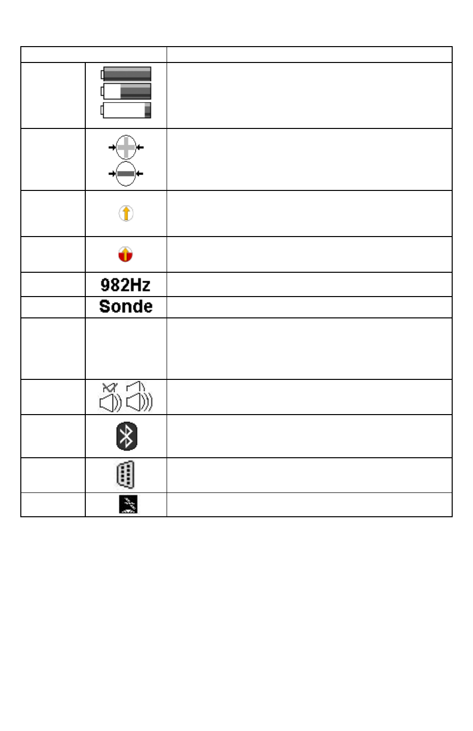
display Icon
description
Battery Level
Displayed as a continuous level from a full 100% charge to 0%.
Signal
Select™
Displayed when activated in direct (conductive) connection or Signal Select
Clamp mode. This icon alerts the user if the receiver detects Signal Select
modulation.
Guidance
Compass™
A single graphical icon that implements three tools aiding locating accuracy –
signal select, distortion alert, and line guidance.
Distortion
Alert™
The Distortion Alert, displayed as a red-filling or emptying circle, denotes when
a non-ideal magnetic field is detected.
Frequency
The active frequency, or the passive band name (power or RF), is always
displayed on the top left of the display.
Locate Mode
In Sonde locate mode, the active mode is displayed on the top left of the
display. Otherwise, line locate mode is active.
Signal Gain
Mode
Auto
Man
Indicates Auto or Manual signal strength mode. In auto mode, signal strength
is measured in decibels (dB). The auto gain mode can be readjusted pressing
the 4-way navigation button up. Manual gain is displayed in a linear scale from
000 to 999. The manual gain can be increased or decreased by pressing the
4-way navigation button right or left, respectively. Manual gain is displayed in
a linear scale from 000 to 999.
Speaker
Volume
Indicates the speaker volume setting - from off to high.
Bluetooth
Indicates an active Bluetooth connection.
RS232
Appears when a host serial cable is connected to R-5000 receiver.
GPS
Indicates the receiver can receive signals from 3 or more satellites (optional).
Not available for AT-5000