Amprobe AT-5000 Underground-Wire-Tracer User Manual
Page 37
35
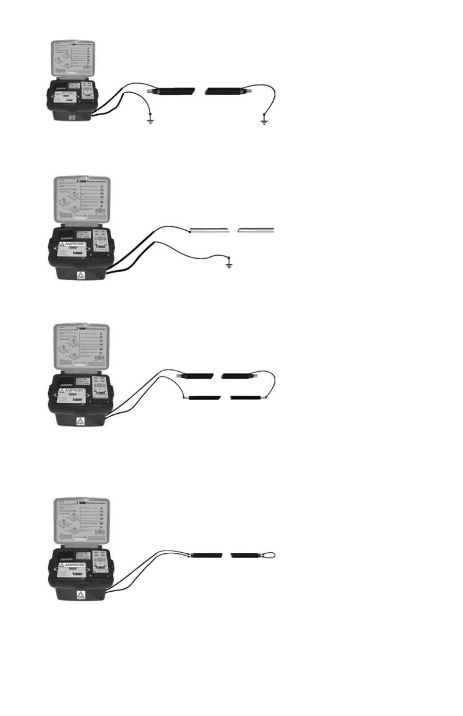
Multiple-Wire Cable (Internal conductor connected or disconnected) with metallic screen and grounding insulation
3.
Metallic Conduit (With or Without Insulation)
4.
The grounding rod and the conduit should be spaced as far apart as possible. Under certain circumstances, optimum positioning
of the grounding rod may require several attempts.
If a return wire is available
5.
The spacing of the return wire should correspond to at least 10 times the depth of the line being located.
Pair of wires (with or without screen) with short circuit at the end of the cable
6.
For twisted cable pair (with a length of lay of the twist greater or equal to the laying depth), the orientation of the cable can
be easily determined.
Adjacent lines which are horizontal to each other Minimum of the reception signal
Lines situated on top of each other vertically Maximum of the reception signal
direct Coupling
Connect the red test lead of the T-5000 transmitter with the conductor to be traced
1.
Connect the black test lead of the T-5000 transmitter to ground using the grounding rod. Alternatively the black test lead
2.
may be clipped to the rim of a valve box or manhole cover.
Switch the T-5000 on
3.
Select the mode of signal transmission
4.
Switch the R-5000 Receiver on
5.