Functional description, Block description, Chapter 3. functional description – Altera QDRII SRAM Controller MegaCore Function User Manual
Page 33: Block description –1
Altera Corporation
MegaCore Version 9.1
3–1
November 2009
3. Functional Description
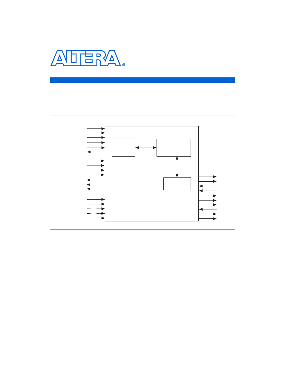
Block
Description
shows a block diagram of the QDR SRAM controller
MegaCore function.
Figure 3–1. QDRII SRAM Controller Block Diagram
Notes to
:
(1)
You can edit the qdrii_ prefix.
The QDRII SRAM Controller comprises the following three parts:
■
The control logic gets read and write requests from the Avalon
®
interface and turn them into QDRII SRAM read and write requests,
with the correct timing and concatenating consecutive addresses
where applicable.
■
The resynchronization and pipeline logic provides the
resynchronization system, the training block, and the optional
pipeline logic.
■
The datapath contains all the I/O and the clock generation.
avl_clk
avl_clk_wr
avl_resetn
dll_delay_ctrl
resynch_clk
avl_addr_wr
avl_byteen_wr
avl_chipselect_wr
avl_data_wr
avl_write
avl_wait_request_wr
avl_addr_rd
avl_byteen_rd
avl_chipselect_rd
avl_read
avl_data_rd
avl_datavalid_rd
avl_wait_request_rd
Control
Logic
(Encrypted)
QDRII SRAM Controller
Datapath
(Clear Text)
Resynchronization
& Pipeline Logic
(Clear Text)
qdrii_a
qdrii_bwsn
qdrii_cq
qdrii_cqn
qdrii_d
qdrii_k
qdrii_kn
qdrii_q
qdrii_rpsn
qdrii_wpns