Altera QDRII SRAM Controller MegaCore Function User Manual
Page 56
3–24
MegaCore Version 9.1
Altera Corporation
QDRII SRAM Controller MegaCore Function User Guide
November 2009
Interfaces & Signals
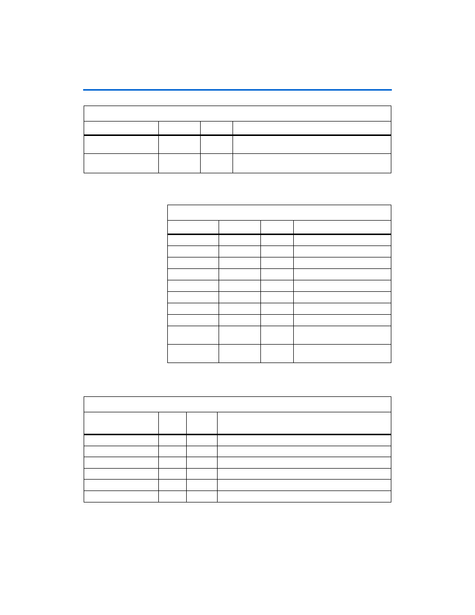
shows the QDRII memory signals.
shows the datapath interface signals.
avl_datavalid_rd
1
Output
Avalon read data valid—the data is sent concurrent to
the signal.
avl_wait_request_
rd
1
Output
Avalon read wait—the transaction does not occur on this
cycle.
Table 3–3. Avalon Read Signals (Part 2 of 2)
Signal
Width (Bits)
Direction
Description
Table 3–4. QDRII Memory Signals
Signal
Width (Bits)
Direction
Description
qdrii_a
21
Output
Address bus.
qdrii_bwsn
8
Output
Byte enable to memory.
qdrii_cq
9
Input
Free running clock from memory.
qdrii_cqn
9
Input
Free running clock from memory.
qdrii_d
72
Output
Data out.
qdrii_k
9
Output
Free running clock to memory.
qdrii_kn
9
Output
Free running clock to memory.
qdrii_q
72
Input
Data in from memory.
qdrii_rpsn
8
Output
Read signal to memory. Active low
and reset in the inactive state.
qdrii_wpsn
8
Output
Write signal to memory. Active low
and reset in the inactive state.
Table 3–5. Datapath Interface Signals (Part 1 of 2)
Name
Width
(Bits)
Direction
Description
clk
–
Input
Clock.
control_a_rd
17:0
Input
Read address from the pipeline and resynchronization logic.
control_a_wr
17:0
Input
Write address from the pipeline and resynchronization logic.
control_bwsn
3:0
Input
Byte enable from the pipeline and resynchronization logic.
control_rpsn
–
Input
Read from the pipeline and resynchronization logic.
control_wdata
35:0
Input
Write data from the pipeline and resynchronization logic.