Altera QDRII SRAM Controller MegaCore Function User Manual
Page 55
Altera Corporation
MegaCore Version 9.1
3–23
November 2009
QDRII SRAM Controller MegaCore Function User Guide
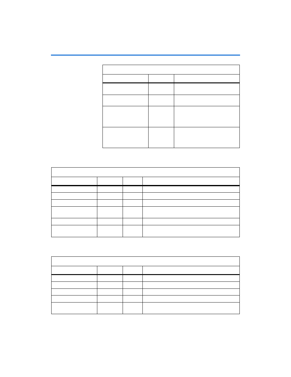
Functional Description
shows the Avalon write signals.
shows the Avalon read signals.
non_dqs_capture
_clock
Input
Non-DQS capture mode clock.
training_done
Output
Asserted when the training of the core
is complete.
training_incorrec
t
Output
The core is nonfunctional.
Asserted when the training reaches
the maximum number of iterations but
fails to adjust the pointers.
training_pattern_
not_found
Output
The core is nonfunctional. The
training must find a positive edge on
the bit 0 of data. The core did not find
this edge.
Table 3–1. System Signals (Part 2 of 2)
Signal
Direction
Description
Table 3–2. Avalon Write Signals
Signal
Width (Bits)
Direction
Description
avl_addr_wr
21
Input
Avalon write address.
avl_byteen_wr
2, 4, 8, or 16
Input
Byte enable (active low).
avl_chipselect_wr
1
Input
Device select for the write port.
avl_data_wr
18, 36, 72,
144, or 288
Input
Avalon data write from master.
avl_write
1
Input
Avalon write request.
avl_wait_request_
wr
1
Output
Avalon write wait—the transaction does not occur on this
cycle.
Table 3–3. Avalon Read Signals (Part 1 of 2)
Signal
Width (Bits)
Direction
Description
avl_addr_rd
21
Input
Avalon read address.
avl_byteen_rd
2 to 16
Input
Byte enable (active low).
avl_chipselect_rd
1
Input
Device select for the read port.
avl_read
1
Input
Avalon read request.
avl_data_rd
18, 36, 72,
144, or 288
Output
Avalon read data to master.