Connecting analog inputs on the in/out1 connector, 35 stac6 hardware manual, Stac-6 – Applied Motion STAC6-C User Manual
Page 35
35
STAC6 Hardware manual
920-0029 Rev. C
5/2/2012
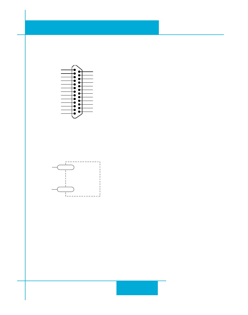
Connecting Analog Inputs on the IN/OUT1 connector
Front View
X COMMON
X7 / CW Limit
X3 / Enable
X5
X4 / Alarm Reset
Analog IN-
Analog IN+
X2 / DIR-
X2 / DIR+
X1 / STEP +
X1 / STEP -
GND
GND
+5V OUT
Y COMMON
Y3 / FAULT
Y2 / MOTION
Y1 / BRAKE
� �
� �
� �
� �
� �
� �
� �
� �
� �
�
�
�
�
�
�
�
�
�
� �
� �
� �
� �
� �
� �
� �
X6 / CCW Limit
IN/OUT 1
+5V OUT
+12V OUT
GND
GND
All STAC6 drives have two analog input pins that can be used separately as two, single-ended analog inputs
or together as one, differential analog input. Whether separate or together, the maximum range that can be
applied to these pins is +/- 10V. The analog input(s) can be used by the drive for a number of dedicated
purposes for controlling the motor or can be used for general purpose analog input signals.
STAC-6
signal return
GND
+10V to -10V
Signal
AIN+
1
13
The analog input can be used for:
• Analog Velocity Mode
• Analog Positioning Mode.
Both of these modes use the analog input for commanding the stepper drive.
Other uses include using an analog signal to stop a move when using any of the “Feed to Sensor” type
moves and waiting on an analog signal using the “Wait on Input”.