42 stac6 hardware manual, Digital outputs, Diagrams of each type of connection follow – Applied Motion STAC6-C User Manual
Page 42
42
STAC6 Hardware manual
920-0029 Rev. C
5/2/2012
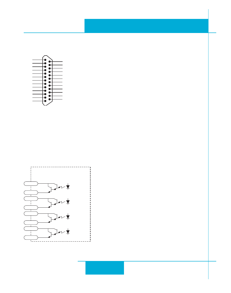
Connecting Digital Outputs on the IN/OUT2 connector
18
17
16
15
14
13
12
11
10
9
8
7
6
5
4
2
3
1
19
20
21
22
23
24
25
+5V
Out 1-
Out 2+
Out 1+
Ain Com
N/C
Ain 1
IN 8-
COM
IN 5
IN 6
IN 7+
IN 8+
IN 7-
IN 4
IN 1
COM
IN 2
COM
IN 3
Out 2-
Out 3+
Out 3-
Out 4+
Out 4-
IN/OUT 2
Digital Outputs
The expanded I/O board adds four additional programmable outputs. The outputs can be used to drive
LEDs, relays and the inputs of other electronic devices like PLCs and counters. On the IN/OUT 2 connector
outputs, both the “+” (collector) and “-” (emitter) terminals of each transistor are available on the connector
pins. This allows you to configure each output for current sourcing or sinking.
IN/OUT 2
OUT1+
OUT1-
OUT2+
OUT2-
OUT3+
OUT3-
OUT4+
OUT4-
Diagrams of each type of connection follow.