Using the quick release pins, Removing the transport covers, Positioning of the load adapters – KLING & FREITAG K&F SEQUENZA 10 W User Manual
Page 17
User's manual
K&F SEQUENZA 10 N/W/B & Flying Frame
KLING & FREITAG GMBH © 2014
Version Version 6.1
Page 17 of 70
7.
Using the Quick Release Pins
The Quick Release Pins are equipped with retaining balls. By pushing the button in the
middle of the pin, you can release these balls and then insert or remove the pin. As long as
you do not push the button in the middle of the pin, you should not be able to pull out the
pin.
8.
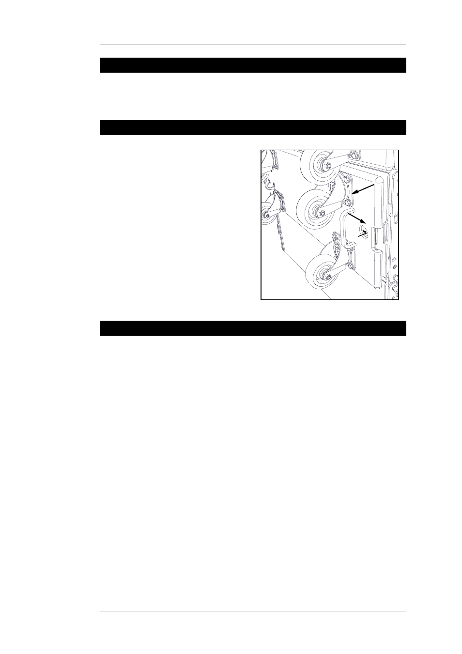
Removing the Transport Covers
In order to remove the transport cover,
push the latch in the round opening
towards the middle of the transport cover
(1), slightly pull the transport cover on
the side of the latch toward you (2), and
remove the cover to the side (3).
When doing this, do not pull the
transport cover towards you too much,
as this could cause the catch on the other
side of the cover to bend.
1
2
3
9.
Positioning of the Load Adapters
You can calculate one- and two-strand riggings with the simulation software CON:SEQUENZA.
For one-strand rigging, use one load adapter; for two-strand rigging, use two load adapters.
The drill holes on the flying frame where the load adapters are to be attached are
determined by the simulation software CON:SEQUENZA. CON:SEQUENZAYou will find the
specifications on the relevant calculation printouts. The specification of the drill hole in the
simulation software refers to the drill hole in the load adapter that is facing the front side of
the frame. The front side of the frame is marked with a sticker (Front).