Front panel familiarisation – XTA 5 Series User Manual
Page 11
✁
✂
✄
☎
✂
✆
✁
✂
✄
☎
✂
✆
✁
✂
✄
☎
✂
✆
✁
✂
✄
☎
✂
✆
Operator’s Manual
Page 11
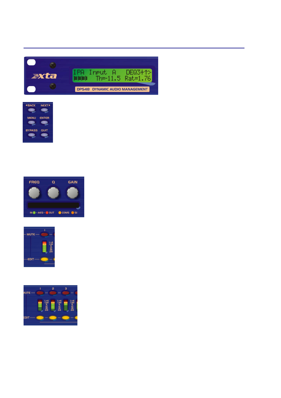
Front Panel Familiarisation
LCD Screen:
Shows, by default, the name of the
last recalled memory on the bottom line of the
screen, and the current routing on the top line.
Also used to show all parameters as they are
edited, and all menu selections.
Control Keys:
Selection and adjustment of parameters.
NEXT key moves forward through list of parameters.
BACK key moves backwards through list of parameters.
MENU
key activates the main menu – a second press selects the last menu edited – a third press selects
the last menu item. In this way, three presses on MENU from the default screen will jump back to the
last parameter adjusted. Selection of different menus is accomplished using the BACK and NEXT keys,
or with the FREQ encoder.
ENTER key enters the chosen menu, confirms selections, and changes filter types when editing
parametric sections.
BYPASS will flatten the currently selected parametric sections, or input graphic equalisers and
dynamics modules. For safety reasons, it is not possible to bypass the high and low pass filter sections.
QUIT
exits menus back to the default screen.
Rotary Encoders:
Three velocity sensitive encoders adjust the relevant parameters as
displayed on the screen.
Memory Card Slot:
Will accept type I or type II PCMCIA SRAM cards and, using an
adapter, Compact Flash cards. This allows the unit to be cloned, memory sets saved,
presets loaded, and firmware updates installed.
Status LEDs:
The four status LEDs show, from left to right, AES inputs selected
(flashing if not locked); AES outputs selected; Comms activity (only illuminates on
messages addressed to this particular unit); and a general-purpose spare indicator.
Input Sections:
Control and monitor input signal paths.
Red MUTE buttons illuminate when pressed and mute audio for that channel.
EDIT buttons illuminate yellow when pressed, and access gain on first press, then last viewed parameter
on second press, then exit on third press.
Input meters show dB from clipping point of the analogue to digital converters. Yellow (0dB) LED
illuminates 3dB from clipping. Red CLIP LED may illuminate independently from the rest of the meter
to show digital overflow. All four CLIP LEDs illuminating indicates internal clipping after the ADC.
Meters also read downwards from the yellow LED to show gain adjustment (reduction or expansion)
when editing DEQ modules – meter shows gain adjustment for current band of DEQ only.
Output Sections:
Control and monitor output signal paths.
Red MUTE buttons illuminate when pressed and mute audio for that channel.
EDIT buttons illuminate yellow when pressed, and access gain on first press, then last
viewed parameter on second press, then exit on third press. Output meters show dB from
limiting. The yellow LED illuminates at the onset of limiting. The red LED illuminates at
4dB into limiting (i.e. 4dB of gain reduction).
Meters also read downwards from the yellow LED to show gain reduction when editing
compressors. These may be left permanently enabled by changing this option in the
DYNAMICS
DYNAMICS
DYNAMICS
DYNAMICS
sub-menu.