XTA 5 Series User Manual
Page 58
Page 58
5 Series
5 Series
5 Series
5 Series Operator’s Manual
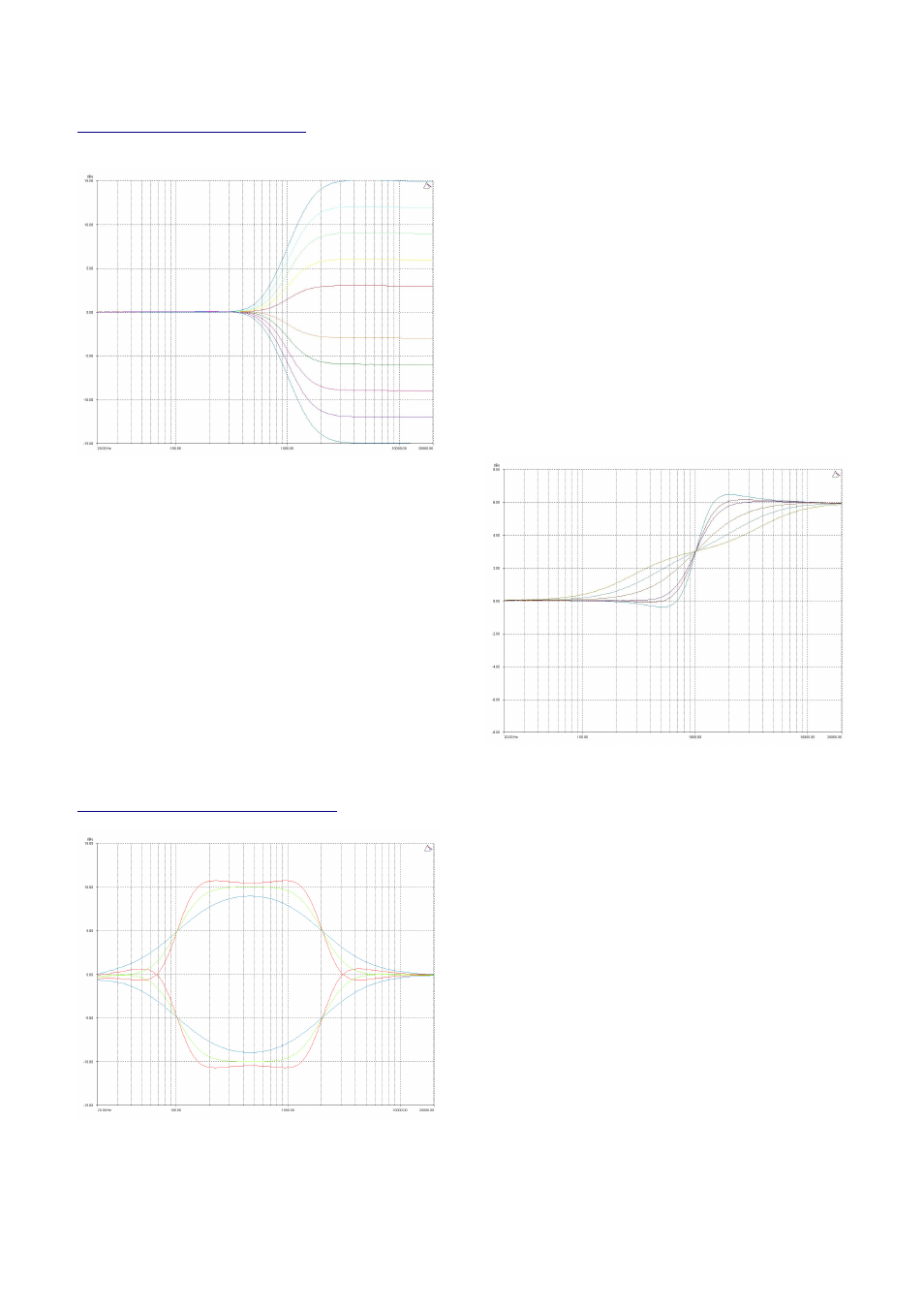
Shelving EQ (High Shelf shown)
InA Input A HSF:1
InA Input A HSF:1
InA Input A HSF:1
InA Input A HSF:1----<
<
<
<
::
1k00Hz Q=3.0 0.0dB
1k00Hz Q=3.0 0.0dB
1k00Hz Q=3.0 0.0dB
1k00Hz Q=3.0 0.0dB
Remember – to change filter types, press BYPASS
BYPASS
BYPASS
BYPASS to bypass
the filter, and then use ENTER
ENTER
ENTER
ENTER to select the filter type.
The shelving EQ has adjustable frequency, ‘Q’ (or Bandwidth)
and Gain controls. These affect a range of frequencies from
the turnover freqency as shown in the graph. For a high shelf,
frequencies above the turnover frequency will be affected.
For a low shelf, frequencies below the turnover frequency will
be affected.
Various levels of cut and boost are shown to the left, along
with various ‘Q’ settings (gain boosts only are show below).
Remember that ‘Q’ is 1/Bandwidth, so the higher the ‘Q’, the
lower the Bandwidth, and the smaller the range of frequencies
affected.
Note that ‘Q’ settings above 0.75 will result in slight
overshoot in the filter response (as seen at the highest setting
to the right). This is normal behaviour and does not indicate
instability.
Creating a Flat-topped EQ Response
To create a flat-topped EQ filter response such as that shown
to the left, use two EQ bands, BOTH configured as low
shelves. For an overall BOOST, set the Lower frequency filter
to BOOST the desired amount, and the Upper frequency filter
to CUT by the same amount.
This example shows one filter at 100Hz and the other at
2kHz, with the 100Hz filter at –10dB, and the 2kHz filter at
+10dB. Varying the ‘Q’ affects the slope of the response –
values above 0.75 will cause overshoot as shown.
Assymetrical responses may be achieved by adjusting the ‘Q’
of each filter independantly.