XTA 5 Series User Manual
Page 24
Page 24
5 Series
5 Series
5 Series
5 Series Operator’s Manual
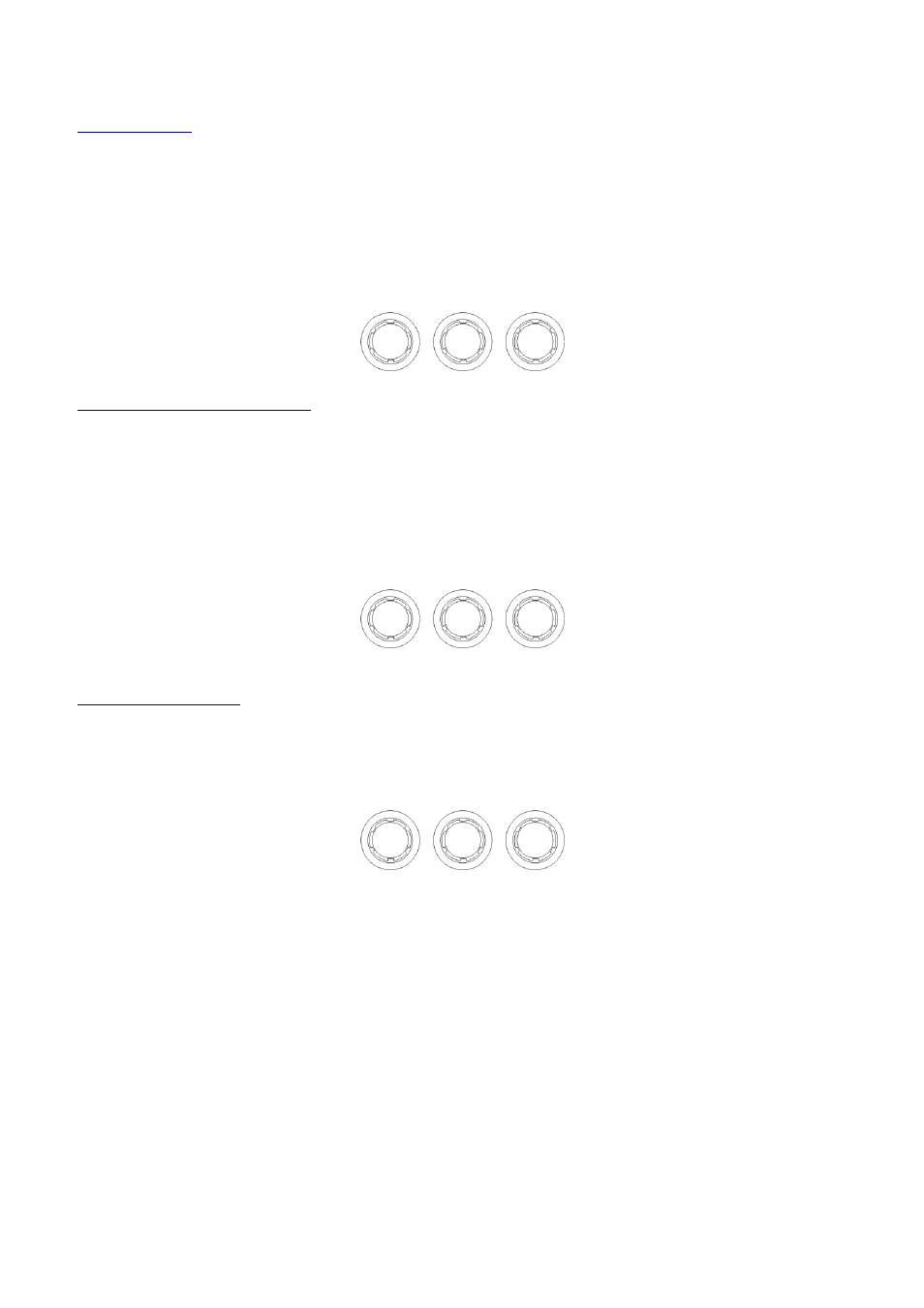
Output Limiter
The limiter on each output has adjustable attack and threshold, with a release time that is selectable to be a multiplier of
the attack time. For example, as shown below, the attack time is 2mS and release is “x16” so 32mS. The attack and
release times can be automatically linked to the high pass filter frequency, so that they are set to correct values for the
output’s frequency range. If this feature is enabled, the display will show
Automatic T/C in
Automatic T/C in
Automatic T/C in
Automatic T/C in
place of the attack
and release times. Selection of automatic time constants is through the
Design a Crossover
Design a Crossover
Design a Crossover
Design a Crossover
wizard, in the
Crossover Sub
Crossover Sub
Crossover Sub
Crossover Sub----Menu
Menu
Menu
Menu
.
OP1 Out
OP1 Out
OP1 Out
OP1 Output 1 Limiter
put 1 Limiter
put 1 Limiter
put 1 Limiter
Atk=2.0mS Rel=x16 +22dB
Atk=2.0mS Rel=x16 +22dB
Atk=2.0mS Rel=x16 +22dB
Atk=2.0mS Rel=x16 +22dB
Attack Release Threshold
Output “D-Max” (Clip) Limiter
The clip limiter on each output is designed to sit at a threshold just above the standard limiter and has a look ahead attack
so that its threshold can never be exceeded. The release time can be automatically linked to the high pass filter frequency,
so that it is set to a value appropriate for the output’s frequency range. If this feature is enabled, the display will show
Rel. = Auto
Rel. = Auto
Rel. = Auto
Rel. = Auto
in place of the release time. Selection of automatic time constants is through the
Design a Crossover
Design a Crossover
Design a Crossover
Design a Crossover
wizard, in the
Crossover Sub
Crossover Sub
Crossover Sub
Crossover Sub----Menu
Menu
Menu
Menu
.
More information about the limiters and their use is given in the section on page 44.
OP1 Output 1 ClipLim
OP1 Output 1 ClipLim
OP1 Output 1 ClipLim
OP1 Output 1 ClipLim
Rel.=Medium 2dB Above
Rel.=Medium 2dB Above
Rel.=Medium 2dB Above
Rel.=Medium 2dB Above
Release Threshold
Output Matrix Mixing
If “full matrix” mode has been enabled (selection of this is through the
Design a Crossover
Design a Crossover
Design a Crossover
Design a Crossover
wizard, in the
Crossover Sub
Crossover Sub
Crossover Sub
Crossover Sub----Menu
Menu
Menu
Menu
) this screen will be shown after the limiters when editing outputs.
OP1 Matrix Gain A
OP1 Matrix Gain A
OP1 Matrix Gain A
OP1 Matrix Gain A
[+14.5] Off Off
[+14.5] Off Off
[+14.5] Off Off
[+14.5] Off Off ----32.8
32.8
32.8
32.8
Gain
Selection of the “send” to this output (cycling between inputs A-D) is achieved by pressing ENTER
ENTER
ENTER
ENTER – the top line will
change to show the relevant send channel for adjustment (
Gain A
Gain A
Gain A
Gain A----D
D
D
D
) and the mix level to adjust will become
bracketed on the bottom line. The gain control will adjust the level to be mixed into this output. One click below
minimum gain (
-
-
-
-40dB
40dB
40dB
40dB
) will mute the send and the gain will be replaced by
Off
Off
Off
Off
as shown above.
Note that ganging is temporarily disabled when the matrix sends screen is shown.