Rear panel connections – XTA 5 Series User Manual
Page 12
Page 12
5 Series
5 Series
5 Series
5 Series Operator’s Manual
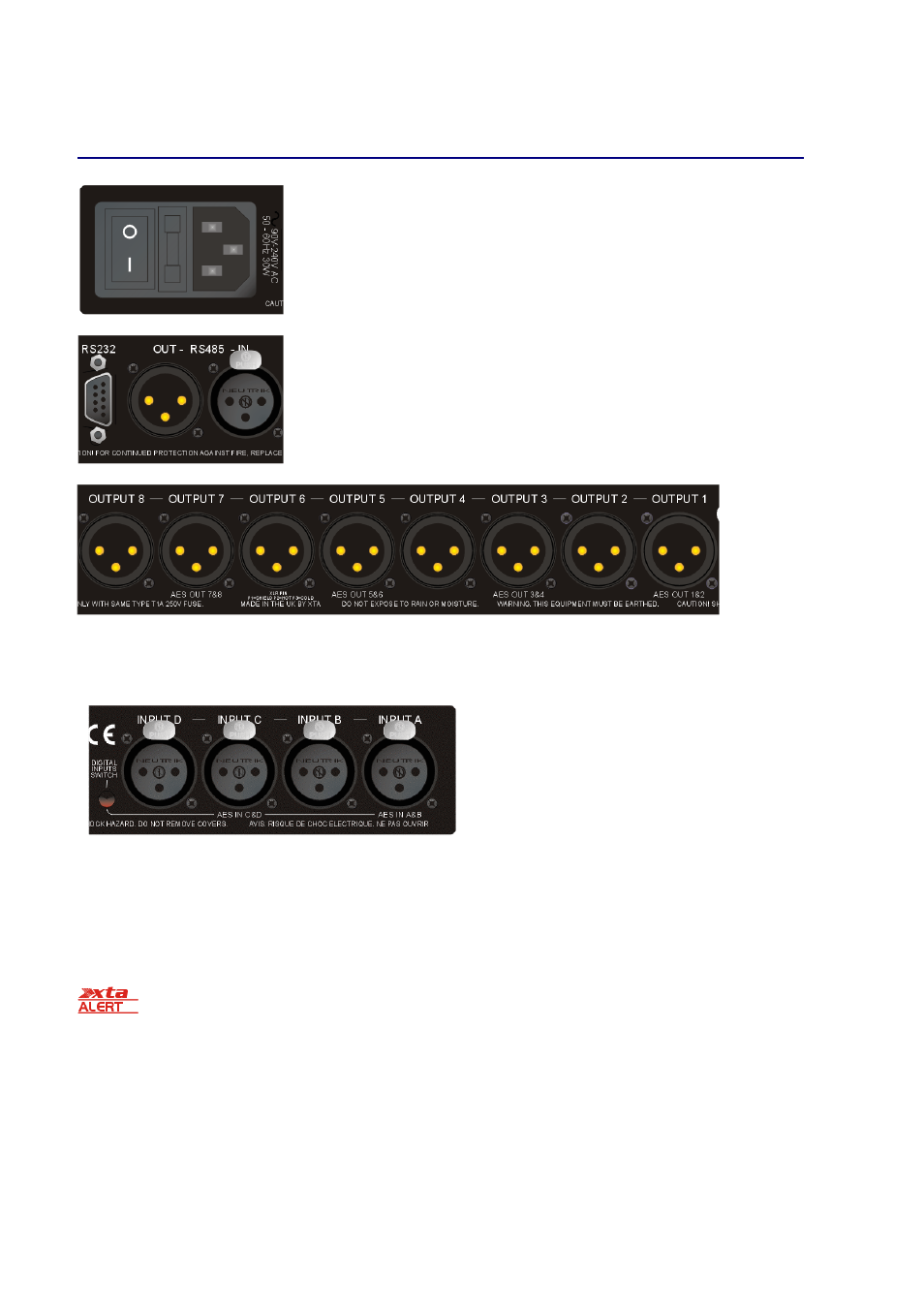
Rear Panel Connections
Power Switch:
turns the unit’s mains supply off and on.
Mains Fuse:
located in a finger-proof holder adjacent to the mains inlet. A spare fuse
is also located in this holder.
Mains Inlet:
connected via a standard IEC socket.
RS232:
RS232 standard via a 9 pin D-type connector, for connection to a PC. Data is
converted to RS485 standard and relayed to slave units via the RS485 sockets.
RS485 In-Out:
XLR sockets. Used for transmission of remote control data over long
distance or multiple unit applications. See page 33 for more information.
For more details on interfaces see our Remote Interface Guide, available on-line.
Audio Outputs:
3 pin XLR sockets are provided for each channel. All are fully balanced, pin 2 hot, 3 cold, 1 screen.
Note the legending on the panel to designate which outputs are used for AES streams when the digital outputs are
enabled. Please see page 36 for more information.
AES Input Switch:
Recessed switch to select AES digital
inputs. Red LED will illuminate in the hole when AES inputs
are selected, along with the corresponding front panel
indicator.
Audio Inputs:
3 pin XLR sockets are provided for each
channel. All are fully balanced, pin 2 hot, 3 cold, 1 screen.
Note the legending on the panel to designate which inputs
are used for AES when the digital inputs are enabled. Please
see page 36 for more information.
Always replace the fuse with the correct type and rating as shown on the rear panel legend.