Campus transmitting antenna installation, Component location & mounting guidelines – American Time Wireless Remote Transmitter User Manual
Page 8
© American Time
8
Wireless Remote Transmitter Installation Manual
Glossary
Appendix
Tr
oubleshooting
Clock
Installation
Transmitter and System Setup
Intr
oduction
Component Location & Mounting Guidelines
Campus Transmitting
Antenna Installation
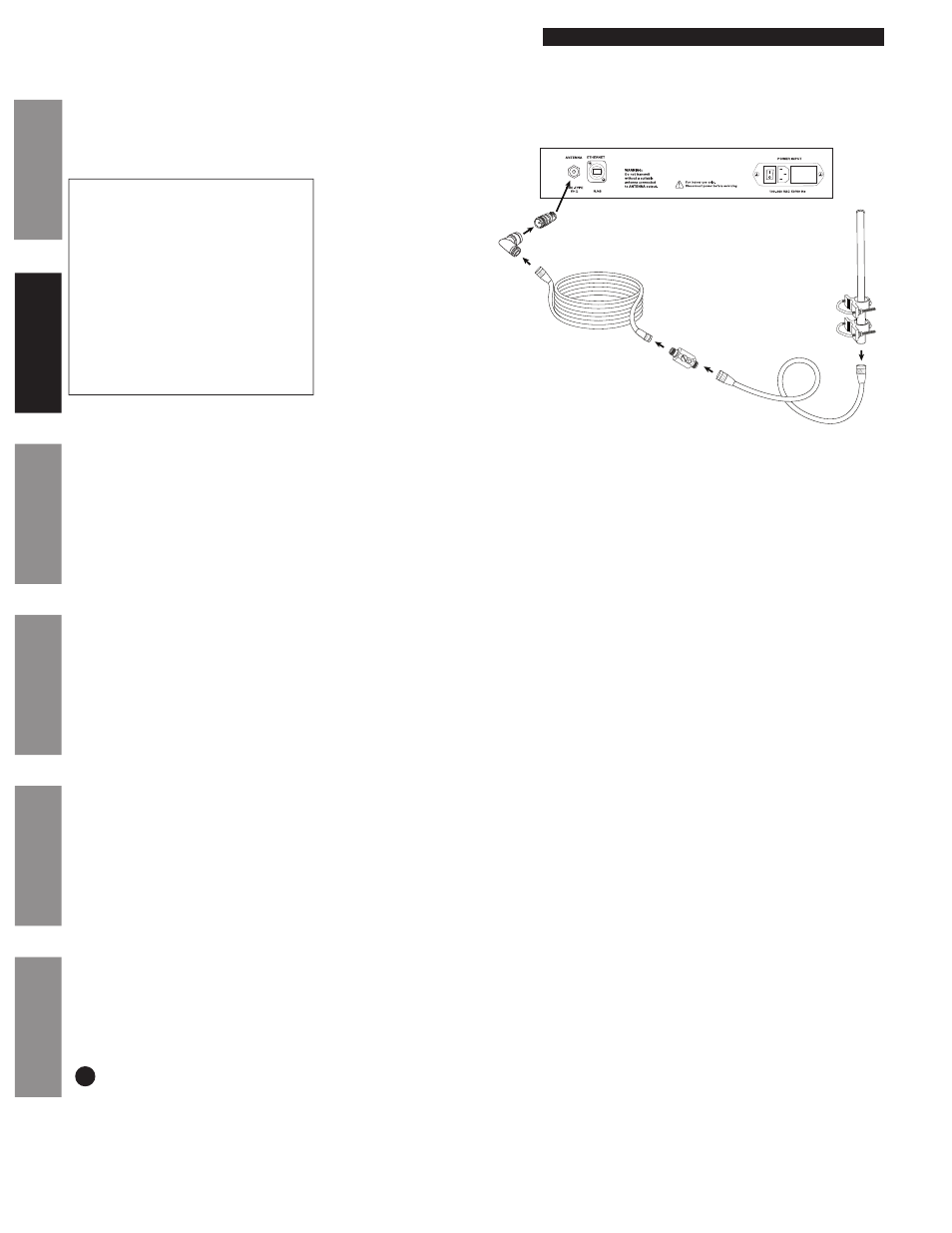
The Campus Antenna kit is recommended for outdoor antenna installations and improved signal coverage. It can be used with any of the
models and is specified when ordering.
The Campus Kit includes:
A. Heavy-duty, outdoor type 26 inch
fiberglass antenna
B. 10 ft. COAX cable
C. Lightning arrestor
D. 50 ft. COAX cable
E. N female to N male right angle
adapter
F. N female to BNC male adapter
(only for direct connection to IQ
Remote Transmitter)
G. Mounting kit
American Time recommends installing the Campus Antenna on a mast at an elevated location outdoors.
n
WARNING: The SiteSync IQ Remote Transmitter should remain powered off until installation of the Campus Antenna is complete.
u
Select a suitable location for the SiteSync IQ Remote Transmitter and the Campus Antenna.
a. Locate the antenna at least 4 ft. away from the Remote Transmitter and other electronic equipment to minimize the potential for
interference caused by the radio frequency energy emitted from the antenna.
b. Place the antenna indoors or outside at a central location on the highest level of the facility (a rooftop penthouse usually works well,
for example).
c. Place the antenna in an area that is easily accessible for maintenance and inspection.
d. Avoid placing the antenna in an area where people will touch it or come within 3 ft. of it during operation of the Remote
Transmitter.
e. Avoid placing the antenna in an area surrounded by large metal objects that could block the radio signal and reduce signal coverage.
f. When installed outdoors, the location of the antenna should be lower than other nearby building features or lightning rods to reduce
the potential for lightning strikes.
g. Identify a location in the proximity of a suitable means for grounding the lightning arrester.
n
Note: Cable lengths should be considered when selecting locations for both the Remote Transmitter and Campus Antenna.
v
Install the Campus Antenna mast (not included) vertically. Mast should be circular and approximately 2 inches in diameter, and should be
made of a non-rusting or rust-resistant rigid material.
w
Attach Campus Antenna
(A) to 10 ft. cable (B) at mast end.
x
Attach mounting kit
(G) to mast at Campus Antenna location.
y
Insert Campus Antenna into mounting kit and fasten set screws.
z
Route the 10 ft. cable
(B) from mast to location of Remote Transmitter. Secure cable with cable ties or other suitable method.
n
Note: Do not bend cable beyond original packaged coil bend.
Connect lightning arrestor
(C) to the 10 ft. cable (B) and to the ground rod (not included).
Connect the 50 ft. cable
(D) to the lightning arrestor (C). If the lightning arrestor is outdoors, seal it and the attached COAX connectors to
prevent moisture from entering.
Connect the N female to N male right angle adapter
(E) to the 50 ft. cable (D).
A. When connecting the Campus Antenna to the Remote Transmitter, use the BNC male connector (F). Connect the N female to N male
right angle adapter
(E) to the N female to BNC male adapter (F), and connect this adapter to the Remote Transmitter.
Ground the lightning arrestor
(C) per the National Electrical Code and any applicable local codes. Seal the COAX connections around the
arrestor to prevent moisture from entering.
n
Note: This lightning arrester is not designed to withstand a direct lightning strike. However,
it can survive lightning strikes in the general area. See Troubleshooting section for information if you suspect the system has been struck
by lightning.
A
B
C
D
E
F
G
11