Figure 4-4: local loop wiring – Auto-Zone Control Systems Auto-Zone Plus Systems Installation & Operation (Version 03A) User Manual
Page 158
Section 4
Auto-Zone Plus
4-8
Start-Up and Troubleshooting
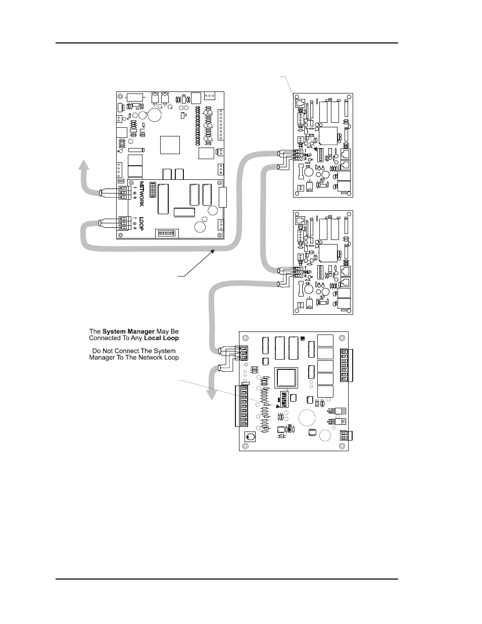
Connect Zone Controllers, CV Units
And The System Manager To This Loop.
Zone Controllers Should Be Connected
To The Loop Coming From The Rooftop Unit
Which Supplies Air For That Controller
HVAC Unit #1
Zone Manager
T
R
SHLD
T
R
SHLD
Local Loop #1
Rs-485 Comm Loop
RELAY
OUTPUT
COM
1-3
OUT
OUT
1
2
COM
4-5
OUT
OUT
OUT
3
4
5
24VAC
GND
PWR
COMM
T
SHLD
LD4
REC.
12V
AIN
1
2
3
4
5
GND
GND
AOUT
AIN
AIN
AIN
AIN
4-5
OUT
COMM
TEST
32K
8K
RAM
EPROM
ADDRESS ADD
PRESSURE
SENSOR
485
COMM
R
YS101564
EW
DO
G
0-
5
VD
C
0-
1
VD
C
From Other
Zone Managers
And Commlink IV
Network
Loop
To Other
Zone Controllers
And
Constant Volume
Units
Local
Loop
Zone Controller
Zone Controller
Constant Volume Unit
Addressing Starts At 18 And Goes To 30
For Constant Volume Units
& Add-On Devices
Addressing Starts At 1 And Ends At 16
For Zone Controllers
Figure 4-4:
Local Loop Wiring