4 pressure sensor voltage – Auto-Zone Control Systems Auto-Zone Plus Systems Installation & Operation (Version 03A) User Manual
Page 206
Section 4
Auto-Zone Plus
4-56
Start-Up and Troubleshooting
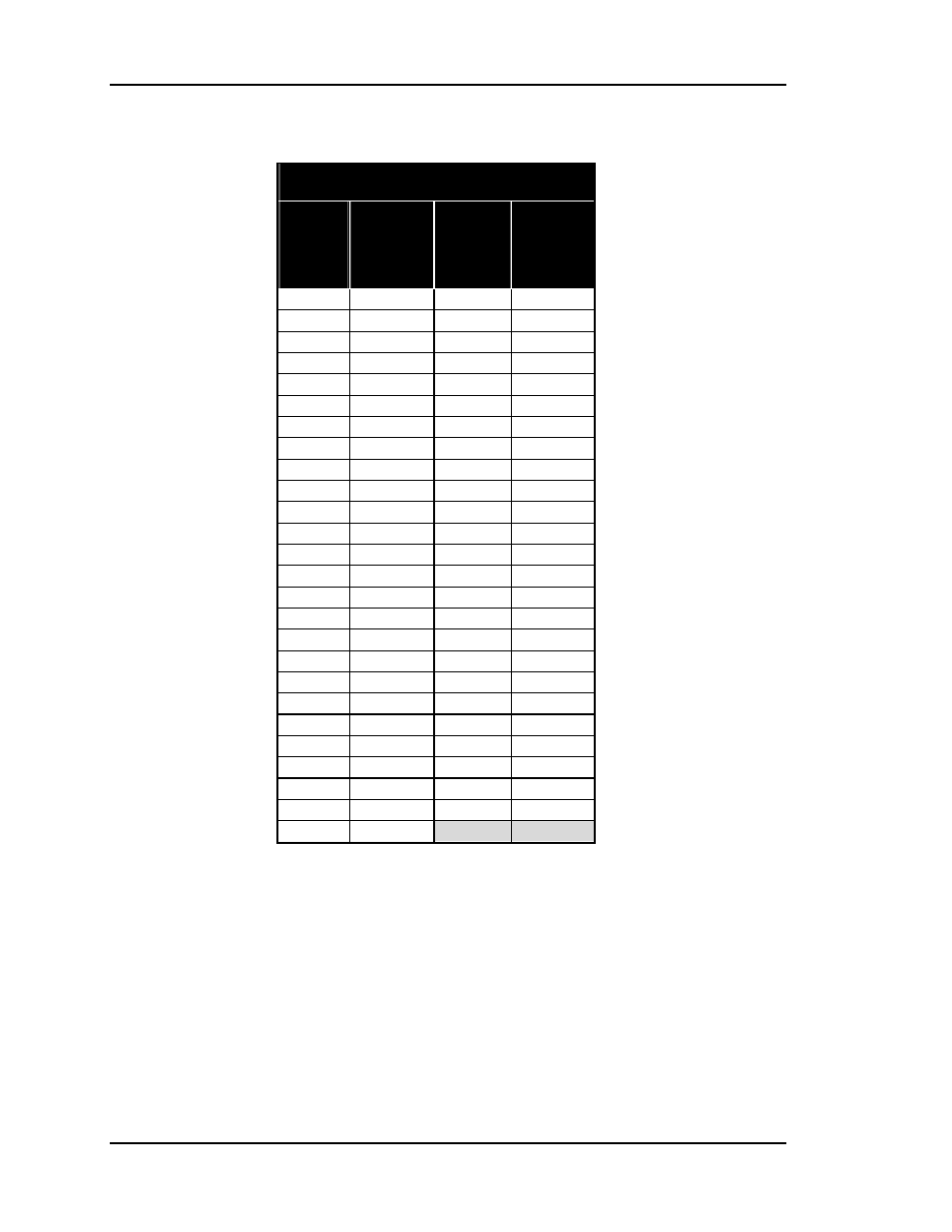
5.4 Pressure Sensor Voltage
Table 4-3:
Pressure Sensor Voltage
OE271 Duct Static Pressure Sensor
Pressure
@
Sensor
(“ W.C.)
Voltage
@
Input
(VDC)
Pressure
@
Sensor
(“ W.C.)
Voltage
@
Input
(VDC)
0.00 0.25 2.60 2.20
0.10 0.33 2.70 2.28
0.20 0.40 2.80 2.35
0.30 0.48 2.90 2.43
0.40 0.55 3.00 2.50
0.50 0.63 3.10 2.58
0.60 0.70 3.20 2.65
0.70 0.78 3.30 2.73
0.80 0.85 3.40 2.80
0.90 0.93 3.50 2.88
1.00 1.00 3.60 2.95
1.10 1.08 3.70 3.03
1.20 1.15 3.80 3.10
1.30 1.23 3.90 3.18
1.40 1.30 4.00 3.25
1.50 1.38 4.10 3.33
1.60 1.45 4.20 3.40
1.70 1.53 4.30 3.48
1.80 1.60 4.40 3.55
1.90 1.68 4.50 3.63
2.00 1.75 4.60 3.70
2.10 1.83 4.70 3.78
2.20 1.90 4.80 3.85
2.30 1.98 4.90 3.93
2.40 2.05 5.00 4.00
2.50 2.13
Notes:
1. Use the voltage column to check the Duct Static Pressure Sensor while connected to
powered controllers. Read voltage with meter set on DC volts. Place the “-”(minus) lead on
GND terminal and the “+”(plus) lead on the
0-5 pin terminal on (JP1) with the jumper
removed. Be sure to replace the jumper after checking.