9 checking the local loop at a controller – Auto-Zone Control Systems Auto-Zone Plus Systems Installation & Operation (Version 03A) User Manual
Page 168
Section 4
Auto-Zone Plus
4-18
Start-Up and Troubleshooting
1.3.9
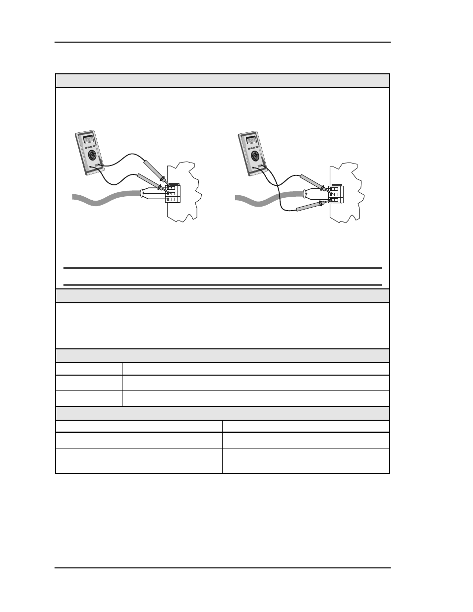
Checking the Local Loop at a Controller
Diagram
Meter Set To Read DC Volts
COMM
LOOP
T
SHLD
R
+
-
T
R
SHLD
+
-
+2.9 VDC
to
+3.1 VDC
COMM
LOOP
T
SHLD
R
+
-
T
R
SHLD
+
-
+1.9 VDC
to
+2.1 VDC
T to SHLD
CV, CV-C
or Zone Controller
CV, CV-C
or Zone Controller
R to SHLD
The indicated readings are typical of a normal operating system. Actual readings may vary
slightly due to the number of units installed and other factors. Any significant deviation
from these values generally indicates a problem.
Note: These tests assume that the controller being checked is connected and powered up.
Overview
Proper loop voltages are essential for reliable communications. It is normal to see
fluctuations on an operating communications loop. The average value should be close to the
acceptable range described below. Values will vary upon initial powerup for about 30-45
seconds. The voltages may fluctuate as normal communications occur.
Measurements
Local Loop
Acceptable Range
T - SHLD
2.9 – 3.1 Volts DC
R - SHLD
1.9 – 2.1 Volts DC
Action
Condition Action
Readings near zero volts
Check for shorted wiring.
If voltages are too high or too low on either
side
One or more devices connected to this loop
have damaged Comm Driver chips.