2 fluid information, Fluid information – Bronkhorst IQ+FLOW (from 01-07-2013) User Manual
Page 22
Bronkhorst High-Tech B.V.
IQ+FLOW
9.17.045
22
20
Valve steering
Setpoint is redirected to Valve Out with
controller idle
21
Analog valve
steering
Analog input is redirected to Valve Out with the
controller idle
22
Valve safe state
After power-up the control mode will be set to 'Analog input' or 'BUS/RS232', depending on the customer's default setting for
analog or digital operation. Except when the actual control mode setting is other than 0, 1, 9 or 18 the actual control mode setting
is maintained. For more information see parameter 'IOStatus', section 4.2.2.
i
www
For dual interface operation or slave factors, see document nr. 9.17.023: Operational instructions for digital
instruments.
4.1.2
Fluid information
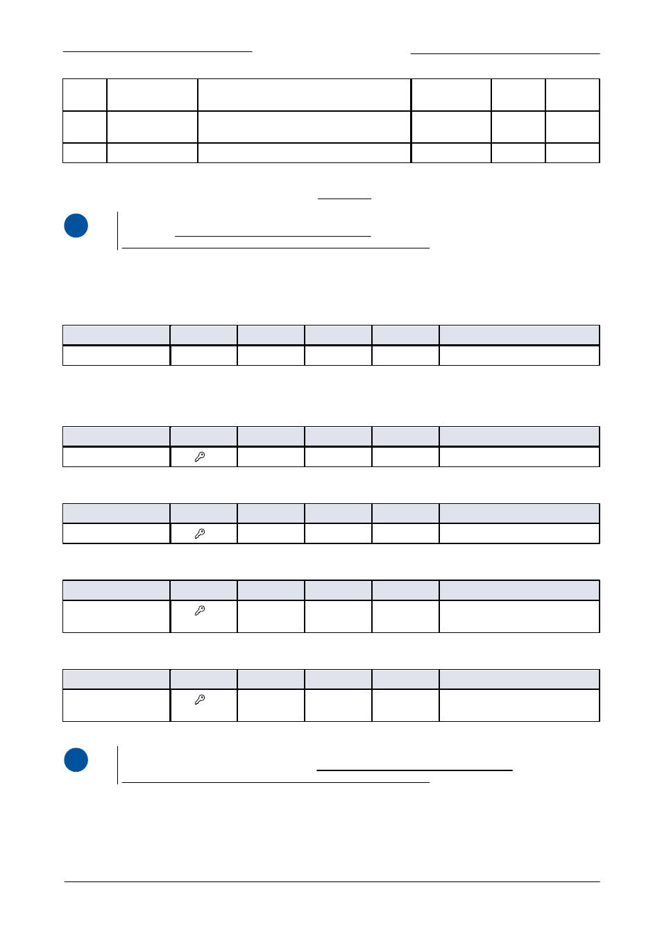
The following parameters give information about the selected fluid range.
Fluid Number
Type
Access
Range
FlowDDE
FLOW-BUS
Modbus
Unsigned char
RW
0…7
24
1/16
0x0030/49
The 'Fluid number' is a pointer to the set of calbration parameters. Each selectable fluid has its own set of calibration parameter
values. Parameter value 0 = fluid 1 and parameter value 7 = fluid 8. Up to eight fluids can be stored in an instrument. Default value
= 0 (fluid 1).
Fluid Name
Type
Access
Range
FlowDDE
FLOW-BUS
Modbus
Unsigned char[10]
RW
-
25
1/17
0x8188…0x818C/33161…33165
This parameter consists of the name of the selected fluid number, e.g. 'Air'.
Fluid Unit
Type
Access
Range
FlowDDE
FLOW-BUS
Modbus
Unsigned char[7]
RW
-
129
1/31
0x81F8…0x81FB/33273…33276
The 'Fluid Unit' can be read by parameter 'Capacity Unit'. This parameter contains the unit in maximal 7 characters.
Fluid Capacity (@100%)
Type
Access
Range
FlowDDE
FLOW-BUS
Modbus
Float
RW
±1E-10…
±1E+10
21
1/13
0x8168…0x8169/33129…33130
Capacity is the maximum value at 100% for direct reading in sensor readout units.
Fluid Capacity (@0%)
Type
Access
Range
FlowDDE
FLOW-BUS
Modbus
Float
RW
±1E-10…
±1E+10
183
33/22
0xA1B0…0xA1B1/41393…41394
This is the capacity zero point for direct reading in sensor readout units.
i
www
For using the 'Capacity Unit Index' or 'Capacity Unit' parameters, see document nr. 9.17.023:
Operational instructions for digital instruments.