5 changing slave address, baud rate and parity, Changing slave address, baud rate and parity – Bronkhorst IQ+FLOW (from 01-07-2013) User Manual
Page 27
Bronkhorst High-Tech B.V.
IQ+FLOW
27
9.17.045
4.2.4
Setting digital output (multi-channel versions only)
The IQ
+
FLOW® multi-channel pc-board is equipped with three digital outputs. The digital outputs can be used for driving shut-off
valves (for instance). The digital outputs can be read or written via the parameter 'IO Switch Status'. The parameters can be set as
indicated in the value table below. Note that this parameter is channel-independent. Each output can be accessed via all channels.
E.g. by writing this parameter via channel 2, it is possible to open/close a shut-off valve located at channel 1.
IO Switch Status
Type
Access
Range
FlowDDE
FLOW-BUS
Modbus
Unsigned long
RW
0…7
288
114/31
0xF2F8/62201
Value
Status output 1
Status output 2
Status output 3
0
Off
Off
Off
1
On
Off
Off
2
Off
On
Off
3
On
On
Off
4
Off
Off
On
5
On
Off
On
6
Off
On
On
7
On
On
On
4.2.5
Changing slave address, baud rate and parity
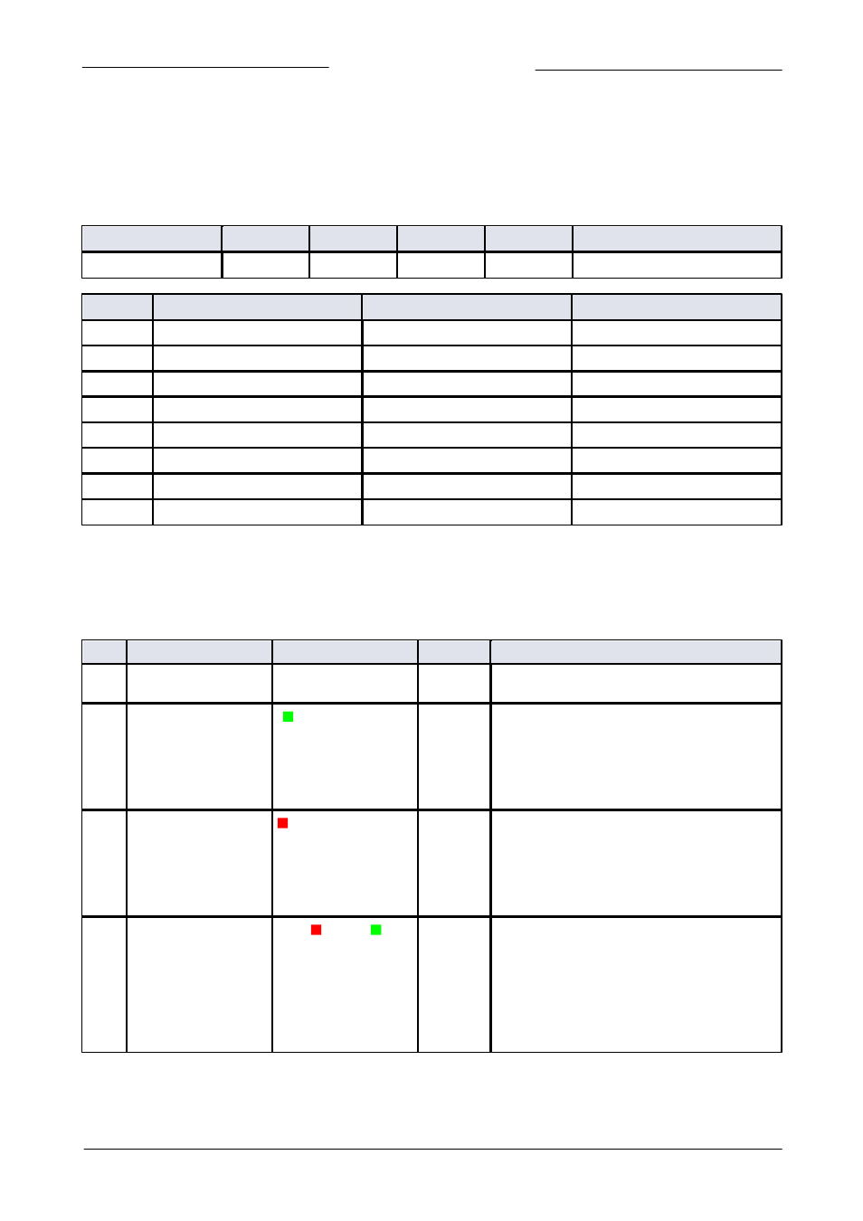
Changing node address or baud rate by micro-switch operation
Press the micro-switch 5x briefly with intervals of max. 1 second in normal running/operation mode. Within the timeout period of
60 seconds it is possible to start changing the node address and baud rate of the instrument.
Step
Action
Indication
Time
Handling
1
Start
Press the switch 5x briefly with intervals of max. 1
second in normal running/operation mode.
2
Set tens of bus address
Green LED flashes
0.1 sec on, 0.1 sec off
count flashes
start when switch
is pressed:
0.5 sec on, 0.5 sec off
timeout:
60 sec
Press switch and count green flashes for tens of
bus address.
Release when wanted amount has been count.
Counts up to max. 12 and than starts at 0 again.
When counting fails, keep switch pressed and
restart counting for next attempt.
3
Set units of bus address
red LED flashes
0.1 sec on, 0.1 sec off
count flashes
start when switch
is pressed:
0.5 sec on, 0.5 sec off
timeout:
60 sec
Press switch and count red flashes for units of bus
address.
Release when wanted amount has been count.
Counts up to max. 9 and than starts at 0 again.
When counting failed, keep switch pressed and
restart counting for next attempt.
4
Set baud rate of field
bus communication.
1 = 9600 Baud
2 = 19200 Baud
3 = 38400 Baud
4 = 56000 Baud
5 = 57600 Baud
6 = 115200 Baud
both red and
green LEDs flashes
0.1 sec on, 0.1 sec off
count flashes
start when switch
is pressed:
0.5 sec on, 0.5 sec off
timeout:
60 sec
Press switch and count red and green flashes for
baud rate setting.
Release when wanted amount has been count.
Counts up to max. 5 and than starts at 0 again.
When counting failed, keep switch pressed and
restart counting for next attempt.
Note: selection of 0 means: No change
Instrument returns to normal running / operation mode. Changes are valid when they are made within the time-out times.