5 display filter, Display filter – Bronkhorst IQ+FLOW (from 01-07-2013) User Manual
Page 24
Bronkhorst High-Tech B.V.
IQ+FLOW
9.17.045
24
Controller Speed (Kspeed)
Type
Access
Range
FlowDDE
FLOW-BUS
Modbus
Float
RW
0…3.4E+38
254
114/30
0xF2F0…0xF2F1/62193…62194
This parameter is the controller speed factor. PID-Kp is multiplied by this factor.
Ti (PID-Ti)
Type
Access
Range
FlowDDE
FLOW-BUS
Modbus
Float
RW
0…1E+10
168
114/22
0xF2B0…0xF2B1/62129…62130
PID controller integration action in seconds. This value should not be changed.
Td (PID-Td)
Type
Access
Range
FlowDDE
FLOW-BUS
Modbus
Float
RW
0…1E+10
169
114/23
0xF2B8…0xF2B9/62137…62138
PID controller differentiation action in seconds. The default value is 0.0. This value should not be changed.
Open from Zero control response (Kopen)
Type
Access
Range
FlowDDE
FLOW-BUS
Modbus
Unsigned char
RW
0…255
165
114/18
0x0E52/3667
Controller response when starting-up from 0% (when valve opens). Value 128 is default and means: no correction.
Otherwise controller speed will be adjusted as follows:
New response = Old response·1.05
(128-Kspeed)
Normal Step response (Knormal)
Type
Access
Range
FlowDDE
FLOW-BUS
Modbus
Unsigned char
RW
0…255
72
114/5
0x0E45/3654
Controller response during normal control (at setpoint step). Value 128 is default and means: no correction.
Otherwise controller speed will be adjusted as follows:
New response = Old response·1.05
(128-Knormal)
Stable Situation control response (Kstable)
Type
Access
Range
FlowDDE
FLOW-BUS
Modbus
Unsigned char
RW
0…255
141
114/17
0x0E51/3666
Controller response when controller is stable (within band of 2% of setpoint). Value 128 is default and means: no correction.
Otherwise controller speed will be adjusted as follows:
New responce = Old responce·1.05
(128-Kstable)
4.1.5
Display filter
The output signal of an IQ
+
FLOW® instrument (measured value) is filtered. The filter has dynamic behaviour: when a change in
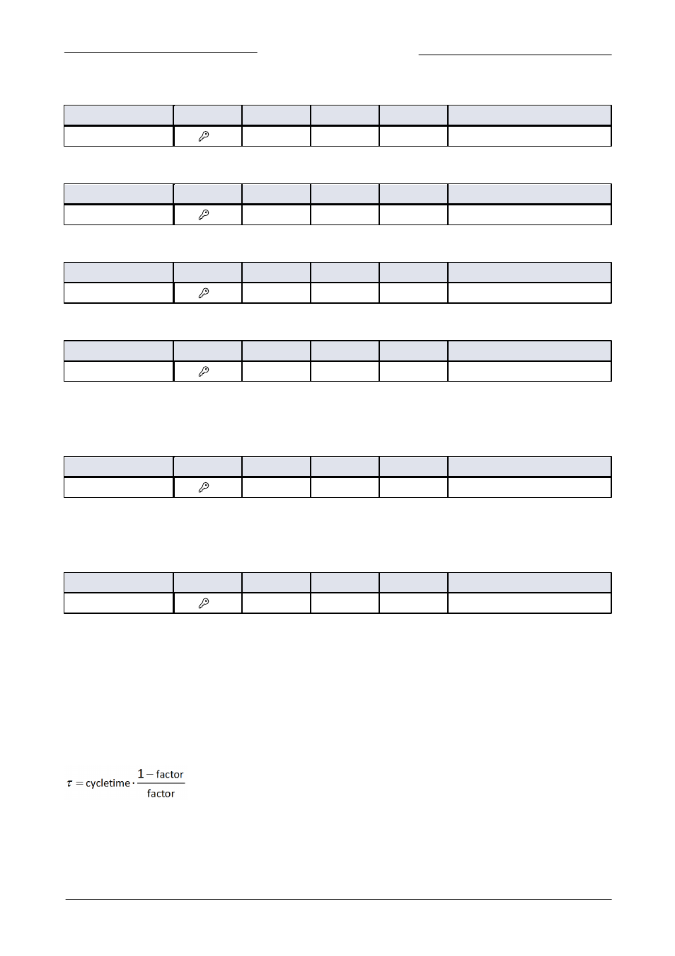
sensor signal is detected, the measured value will be less filtered than when the sensor signal is constant and stable. There are two
filter constants: Static Display Factor and Dynamic Display Factor. These two factors can be transformed into time constants using
the following formula:
The measured value is filtered with a first order low pass filter with a filter time constant between the two ô values.