Appendix b redundant systems, Redundant system, Appendix b. redundant systems – Comtech EF Data CSAT-6070 User Manual
Page 83: B.1 r, Edundant, Ystem, Figure b-1. typical csat redundant system
Appendix B. REDUNDANT SYSTEMS
B.1 Redundant System ............................ B-1
B.2 RSU-5060 Operation ......................... B-7
B.3 Configuring A Redundant System ... B-10
The CSAT-6070, 50 Watt C-Band Transceiver is capable of operating in both
stand-alone and redundant configurations. The CSAT fully redundant system
provides automatic detection, switching, and status for both its configuration and
health. The system is designed such that stand-alone operation is a functional
sub-set of the fully redundant CSAT system. This provides the user with
transparent functionality regardless of the mode or complexity the system has
been setup to operate in.
B.1 R
EDUNDANT
S
YSTEM
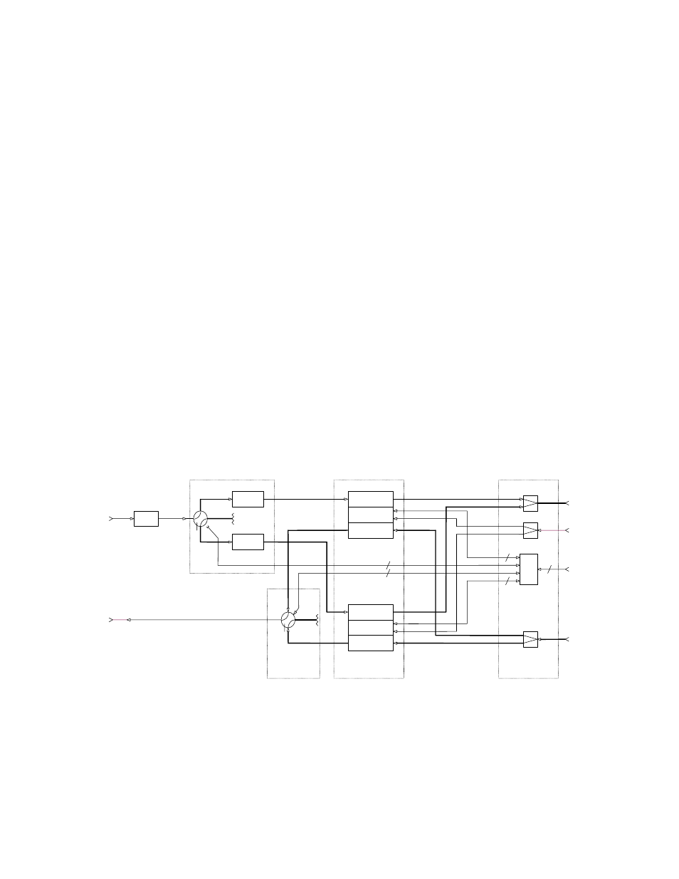
Figure B-1 provides a block diagram for a typical CSAT redundant system.
DOWN
CONV
RF IN
CSAT
LNA 2
M&C
RF OUT
IF IN
UP
CONV
EXT REF
DOWN
CONV
RF IN
IF OUT
CSAT
M&C
IF IN
UP
CONV
Com
EXT REF
CONT
UNIT
Com
IF OUT
19
70 MHz
OUTPUT
70 MHz
INTPUT
10 MHz
INPU
OPTIONAL
RF
FROM
FEED
RF
TO
COM
TRANSCEIVER
6
RF OUT
WG
LNA WG SWITCH
CPR13
7
RSU-5060
Tx WG SWITCH
Tx
FILTER
OPTIONAL
OPTIONAL
LNA 1
CPR22
9 WG
19
19
6
CPR13
7
CPR13
7
A1
A2
W1
W1
C1
C1
CPR22
9
CPR22
9
W3
W3
A3
A4
A4
W2
CPR22
9
T1
T2
C4
C4
C4
C4
C5
C5
C2
C3
FEED
Figure B-1. Typical CSAT Redundant System
B-1