Rf signal conversion, Downconverter, D.1 rf s – Comtech EF Data CSAT-6070 User Manual
Page 98: D.1.1 d, Ignal, Onversion, Ownconverter
50 Watt C-Band Transceiver
Revision 0
Theory of Operation
MN/CSAT6070505.IOM
D.1 RF S
IGNAL
C
ONVERSION
D.1.1 D
OWNCONVERTER
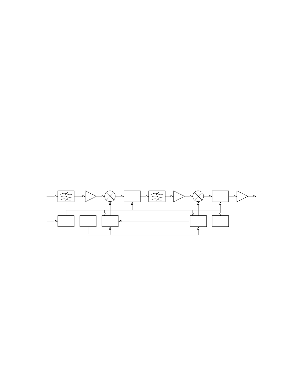
The RF input to the downconverter is in the 3400 to 4200 MHz frequency range at a
typical level of -45 dBm. The input signal is mixed down to the 1110 MHz IF in the first
conversion mixer. High side LO injection is used for this mixing process. It is provided
by the downconverter RFLO synthesizer in the 4510 to 5310 MHz frequency range in
1.000 or 2.500 MHz steps. Both step sizes are automatically selectable.
IF filtering is provided by the 1110 MHz BPF. It is just wide enough to pass the 36 MHz
bandwidth of the desired signal while maintaining more than adequate amplitude and
group delay flatness. At the same time, it is narrow enough to provide the necessary
rejection to the image, the RFLO, and other spurious signals. The second mixer operates
at a fixed input frequency of 1110 MHz. It operates with high side LO injection at 1180
MHz provided by the downconverter IFLO and converts the IF signal down to the 70
±18 MHz output frequency.
RFLO
IFLO
10 M Hz
REFERENCE
1110 M Hz BPF
1180 M Hz
4510 -
3400 -
5310 M Hz
3400 - 4200 M Hz
1180 M Hz
70 +/ - 18 M Hz
M & C
POWER
SUP PLY
VA R
ATTEN
VAR
ATTEN
4200 M Hz
COM
Figure D-1 Functional block diagram of the downconverter section
D-2