Step 2 – connecting the audio wiring, Main audio – r1, Auxiliary audio – r2 – Digital Alert Systems DASDEC-II QUICK START UP GUIDE User Manual
Page 8: Main audio – l1, Auxiliary audio – l2, Common ground
Quick Start Guide for Your DASDEC II
Page 8 of 40
12) The IP Address is now set. All further programming will be accessed through the DASDEC-
II’s embedded website by typing its assigned IP Address into an Internet browser on a
computer on the same network.
Step 2 – Connecting the Audio Wiring
DASDEC™ EAS Monitoring Inputs
Quick Wiring / Configuration Guide
Overview
1.
ALL units have the F-connectors, but NOT all units have the internal radios.
Externally - If the unit shipped with caps over the antenna inputs then it does not contain radios.
Internally - under Setup > Audio units with internal radios will have a “Radio Tuners” tab available
2.
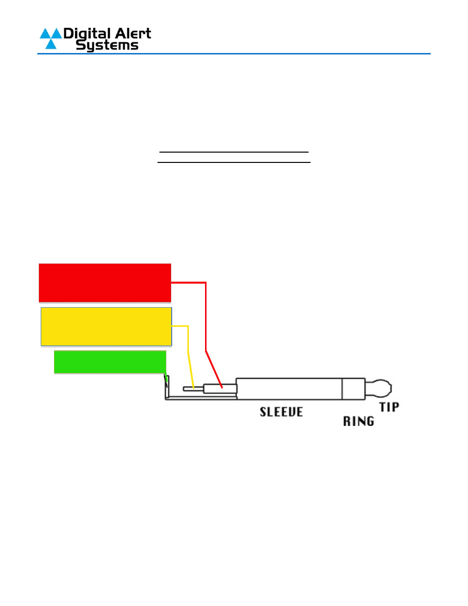
Wiring of the 1/8” mini stereo input audio connectors is shown in Figure 1.
Tip is Left input
Ring is Right input
Sleeve is common ground
Figure 1: Wiring diagram for 1/8 mini stereo plugs
3.
All monitoring inputs are mono only
4.
Inputs use “blue” 1/8 mini plug inputs on the rear panel
5.
Units with the EXP-EAS expanded audio inputs have an additional Auxiliary 2 input board for two (2)
additional inputs and expanded selections under the Setup > Audio > Decoder Audio tab. Following
similar settings for Auxiliary 1 noting this provides line in only connections.
6.
DASLC and DASLCR models do not have Auxiliary Inputs
Section continues on next page
Main Audio – R1
Auxiliary Audio – R2
Main Audio – L1
Auxiliary Audio – L2
Common Ground