Combustion overview – Fieldpiece HG3 - Wireless HVAC Guide System Analyzer User Manual
Page 18
www.fieldpiece.com www.fieldpiece.com www.fieldpiece.com www.fieldpiece.com www.fieldpiece.com www.fieldpiece.com www.fieldpiece.com www.fieldpiece.com www.fieldpiece.com www.fieldpiece.com www.fieldpiece.com
3 4
3 5
4.1
Combustion Overview
Combustion test helps you determine the effectiveness of the combus-
tion by analysis of combustion products and temperature.
The Combustion test will only tell you about combustion and does not
take into account any losses from poor insulation, or cycling and standby
losses. It does not measure any losses in the distribution system such as unin-
sulated hydronic piping, air duct leakage or insulation levels.
Properly tuned gas combustion equipment will produce little or no car-
bon monoxide, no soot, and will consume less fuel.
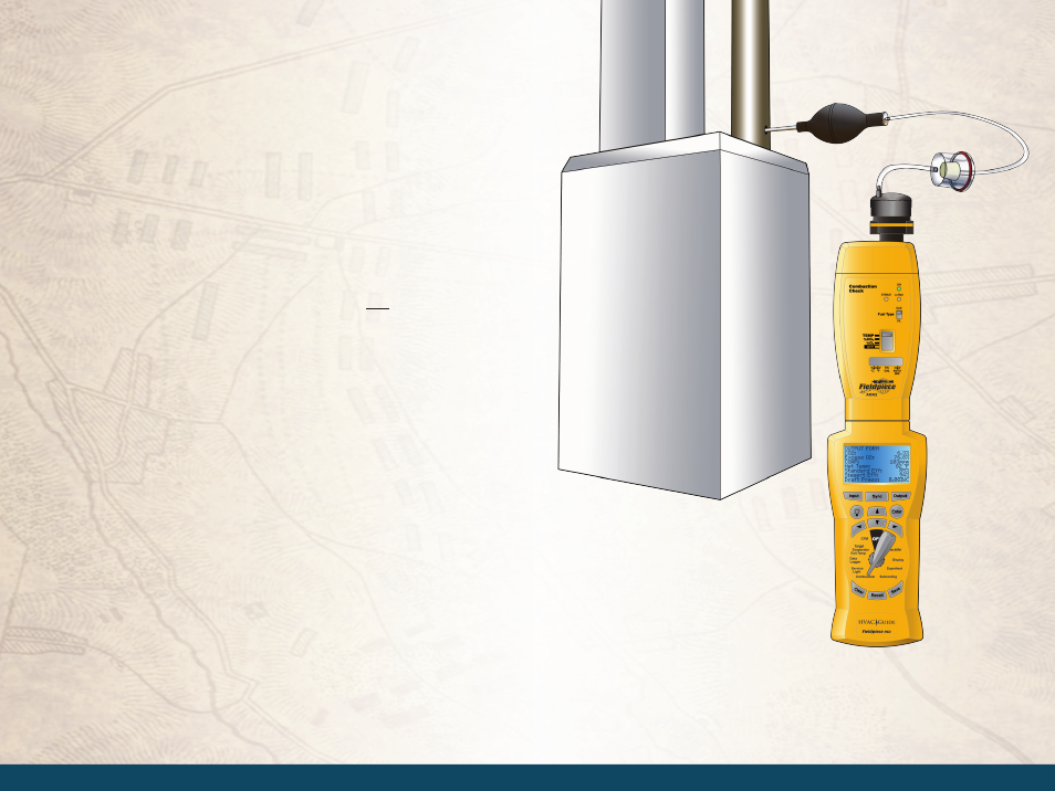
Combustion gases should be sampled close to the exit from the heat ex-
changer within an area where all gases would be well mixed and before dilu-
tion air enters the venting systems (i.e. draft hoods, barometric dampers, etc).
Testing within 18 inches of the breech is a typical location for most oil-fired
equipment. If the appliance is an atmospheric gas type with a draft hood, the
test would be taken in the top flue passage prior to mixing with dilution air.
After testing is complete, the hole in the flue/stack must be plugged ap-
propriately.
Use the HG3, AOX2, AOXP2, and a flue
gas CO detector to perform combus-
tion analysis.