1 gearing and clutching removal. c – Flowserve QX Limitorque User Manual
Page 31
31
Limitorque QX Electronic Actuator FCD LMENIM3314-00 – 5/11
flowserve.com
4.4.1 Gearing and Clutching Removal.
c
WARNING: Potential to operate while dangerous mechanical parts are exposed during subassembly removal.
To prevent injury, turn off all power sources to actuator before removing top-mounted handwheel assembly.
Power sources may include main power or control power.
Step 1, Declutch lever spring return assembly.
Using a M3 hex key, remove the M4 screw (#9-2) and remove bracket (#9-12). Note that spring may be removed from
bracket before removing screw (#9-2) using needle nose pliers. Using a M2.5 hex key remove M3 screw (#9-14),
spring (#9-2) and spacer (9-15) from declutch shaft.
Step 2, Declutch lever, Clutch fork and clutch shaft subassembly.
Using a M2.5 hex key remove M3 screw (#9-10) holding clutch fork (#7) subassembly and declutch lever (#9-9) in
place. Remove declutch lever (#9-9) and ‘O’-ring (#9-8) by sliding lever up and out of housing. Gently pull out the
clutch shaft subassembly (#6) and clutch fork subassembly (#7) out of unit thru the handwheel cover bore.
Step 3, Spur idler subassembly. QX-3/4/5 only.
Gently pull out spur idler subassembly (#8) out thru handwheel cover bore.
Step 4, Gear plate.
Using a M3 hex key, remove the two M4 screws (#9-5) holding in gear plate (#9-4) and remove.
Step 5, Declutch bracket.
Using a M3 hex key, remove the two M4 screws (#9-7) holding declutch bracket (#9-6) in place and remove.
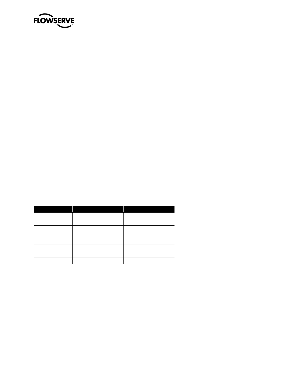
Table 4.11 - Clutch Shaft Subassembly, Item 6. QX-1 & 2
ITEM NUMBER
DESCRIPTION
QTY.
6-1
CLUTCH SHAFT
1
6-2
MOTOR CLUTCH GEAR
1
6-3
PINION
1
6-4
RETAINING RING
1
6-5
CLUTCH
1
6-6
COMPRESSION SPRING
1
6-7
WASHER
1
6-8
RETAINING RING
1