Figure 6.14 - option board assembly – Flowserve QX Limitorque User Manual

Page 66

Advertising
background image

Limitorque QX Electronic Actuator FCD LMENIM3314-00 – 5/11

66

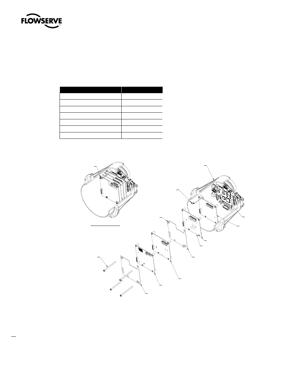
STEP 12 – ALIGNMENT OF OPTION BOARDS INTO LCS/MAIN BOARD

Line up screw sockets and stack the boards so that J7 (option board pins and sockets) fits in with the main board
or any boards that are installed previously. Place shield so sockets match up with cuts in shield. If DeviceNet board
(61-825-0058-4) is used, position grounding wire on top of shield before fastening screws. Fasten four screws, then
align in cover and install to main housing. Please refer to Table 6.10 for the connector numbers.

Table 6.10 - Control Board Connectors

Control Board

Connector Number

DeviceNet

X1

Foundation Fieldbus

X1

Profibus PA

X1

PBDP

X1

Digital Out

J2

Modbus/DDC

X1

Analog

J2

Figure 6.14 - Option Board Assembly



































































Advertising