Automax logix 3200iq digital positioner – Flowserve Logix 3200IQ Digital Positioner User Manual
Page 13
Colors ID
Indication and Resolution
Flowserve Corporation
1350 N. Mountain Springs Parkway
1978 Foreman Dr.
Flow Control Division
Springville, Utah 84663-3004
Cookville, TN 38501
www.flowserve.com
Phone: 801 489 2233
Phone: 931 432 4021
FCD AXAIM3200-00 9/04
Page: 13 of 32
© 2004, Flowserve Corporation, Printed in USA
Automax Logix 3200IQ Digital Positioner
Installation, Operation and Maintenance Instructions
R - - -
Any sequence starting with a red light indicates that there is
an operational problem with the unit.
RGRR
24
Position deviation (user-set) - The position has exceeded
user-defined error band between command and position.
RGYY
25
Pressure reading out of range - The internal pressure
sensors are either saturated with a pressure over 150 psi or
the sensor has failed. Check supply pressure and if OK
check the pressure sensor board connections and replace
pressure sensor board if necessary.
RGYR
26
Loss of supply pressure - The positioner has determined
that the supply pressure is below 15 psi. Check the supply
pressure and if OK check the pressure sensor board
connections and replace pressure sensor board if
necessary. Minimum recommended supply pressure is
30 psi for proper operation.
RYYY
27
Pilot relay non-motion alert - Check to make sure the air
supply is connected. Also check the internal wiring
harnesses for good connections. This error may be cleared
by briefly pushing the QUICK-CAL button, which will force
the positioner to use the parameters from the last good
calibration. If the positioner still does not operate replace
the pneumatic relay assembly.
RYYR
28
Pilot relay lower position alert - Check to make sure the
air supply is connected. Also check the internal wiring
harnesses for good connections. This error may be cleared
by briefly pushing the QUICK-CAL button, which will force
the positioner to use the parameters from the last good
calibration. If the positioner still does not operate replace
the pneumatic relay assembly.
RYRY
29
Pilot relay upper position alert - Check to make sure the
air supply is connected. Also check the internal wiring
harnesses for good connections. This error may be cleared
by briefly pushing the QUICK-CAL button, which will force
the positioner to use the parameters from the last good
calibration. If the positioner still does not operate replace
the pneumatic relay assembly.
RRGG
30
Watchdog timer timeout (also listed as internal voltage
reference) - This is often caused when intermittent
operation occurs when connecting power. Remove power
and then reconnect to clear. If problem persists it is a bad
electronic assembly, replace.
RRYG
31
Internal temperature alert - The internal positioner
temperature is currently exceeding operational limits of
-40°F (-40°C) or 185°F (85°C).
RRYY
32
Piezo voltage error - Bad electronic assembly, replace.
RRYR
33
Internal voltage reference error - Indicates that the circuit
board is drawing too much power. Check internal wiring and
connectors for electrical shorts – if no shorts are present,
replace the electronic assembly.
RRRY
34
NV RAM checksum error - The checksum of the internal
data was not updated correctly. Cycle power and complete
a QUICK-CAL if error persists. Check internal data to verify
correct settings. If the error still occurs, replace the
electronic assembly.
Version Number Checking
The version number of the embedded code may be
checked at any time except during a calibration by holding
down the up arrow Jog button (
↑
). This will not alter the
operation of the unit other than to change the blink
sequence to three blinks indicating the major version
number. Holding the down arrow Jog button (
↓
) will give
the minor version number without affecting operation.
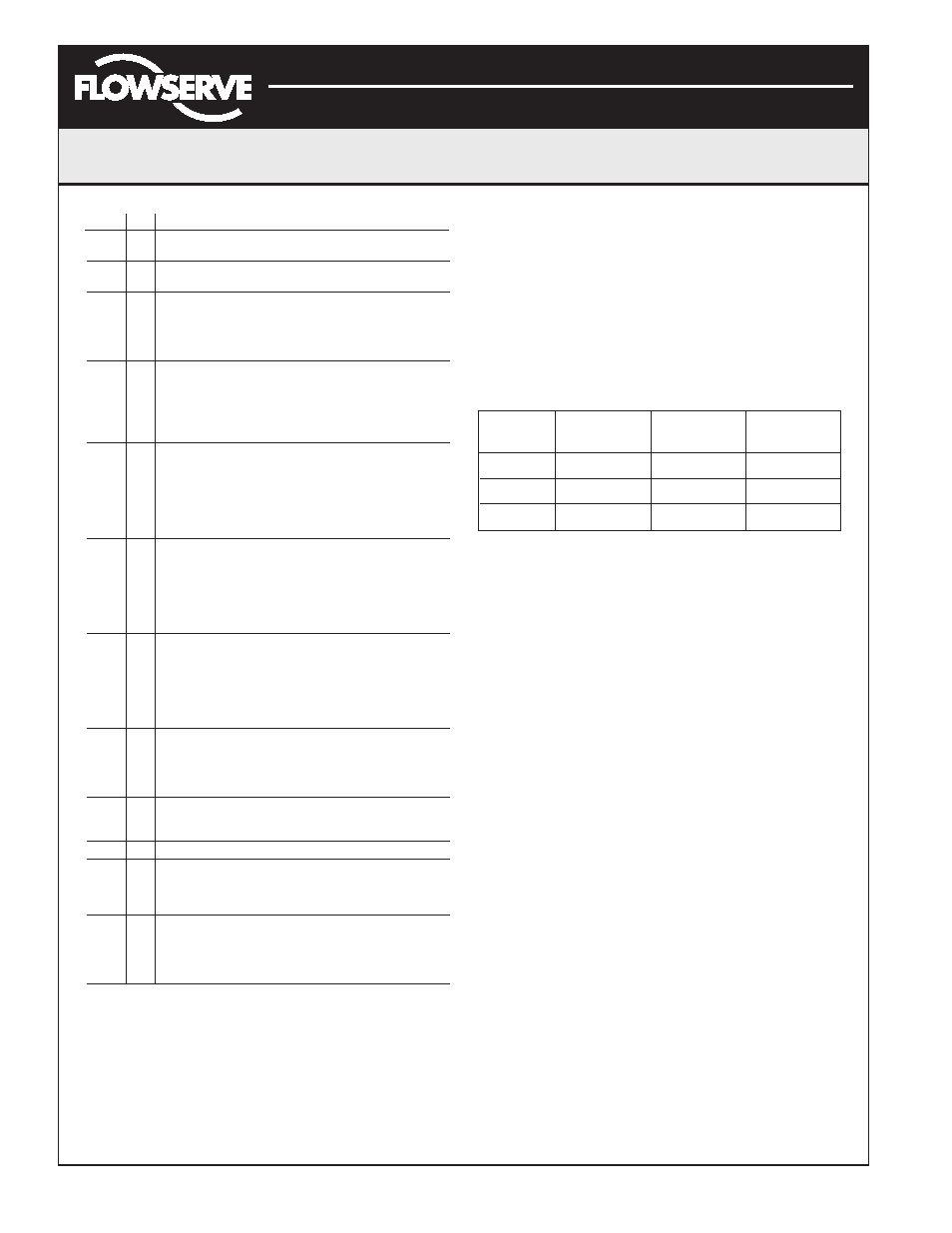
The version codes are interpreted by adding up the
numbers assigned according to the following table:
Color
First Second Third
blink value
blink value
blink value
Green
0
0
0
Yellow
9
3
1
Red
18
6
2
For example if holding the up arrow Jog button (
↑
) gave a
G-G-R code, and holding the down arrow Jog button (
↓
)
gave a Y-Y-G code then the resulting version number
would be (0+0+2).(9+3+0) or version 2.12.
SoftTools
™
Configuration and Diagnostic Software
and HART 275/375 Handheld Communicator
Flowserve Corporation has written custom configuration
and diagnostic software for the Logix 3200IQ digital
positioner called SoftTools. This software and the
SoftTools Quick Start Guide are available from a
Flowserve representative.
The Logix 3200IQ digital positioner supports and is
supported by the HART 275/375 Handheld Communicator.
The Device Description (DD) files and the manuals listed
below can be obtained from the HART Communication
Foundation or from your Flowserve representative. For
more information please see the following guides:
• Product Manual for the HART Communicator.
• Logix 3200IQ Digital Positioner with HART 275/375
Communicator User Guide.
Diagnostic features such as the datalog, signature tests,
and ramp tests are performed using the SoftTools
software. Certain calibration features such as loop
calibration, analog output calibration and actuator
pressure sensor calibrations are performed using the
HART 275/375 Handheld Communicator or using
diagnostic software such as SoftTools.