Automax logix 3200iq digital positioner – Flowserve Logix 3200IQ Digital Positioner User Manual
Page 19
Flowserve Corporation
1350 N. Mountain Springs Parkway
1978 Foreman Dr.
Flow Control Division
Springville, Utah 84663-3004
Cookville, TN 38501
www.flowserve.com
Phone: 801 489 2233
Phone: 931 432 4021
FCD AXAIM3200-00 9/04
Page: 19 of 32
© 2004, Flowserve Corporation, Printed in USA
Automax Logix 3200IQ Digital Positioner
Installation, Operation and Maintenance Instructions
3. Remove the main cover.
4. Remove the plastic board cover by removing the three
retaining screws (see Figure 18).
5. Disconnect the position sensor wires from the main
PCB assembly.
6. Remove the two rotary position sensor-retaining
screws and lift the sensor out of the housing.
7. Turn the new position sensor shaft until the dot on the
side of the shaft is aligned with the wires on the side of
the position sensor (Figure 21).
8. Insert the position sensor into the shaft with the wires
pointing toward the main PCB assembly. Turn the
position sensor clockwise until bolting slots align with
the housing screw holes and the wires on the sensor
protrude over the main PCB assembly.
Note: Do not mix the position sensor with those from
older Logix positioners. Older models contain sensors
with different ranges that will not work in the Logix
3200IQ model. The wires on the Logix 3200IQ
position sensor are red, white and black.
9. Carefully center the position sensor on the shaft bore,
insert and tighten the screws. Do not overtighten.
10. Route the wires along the side of the position sensor
and reconnect to the main PCB assembly.
11. Install the plastic board cover. Insert the three retaining
screws through the plastic cover into the threaded
boss and tighten evenly, using a Phillips screwdriver.
Do not overtighten (see Figure 18).
12. Reinstall all covers.
13. Reconnect power and air supply to the positioner and
perform a stroke calibration.
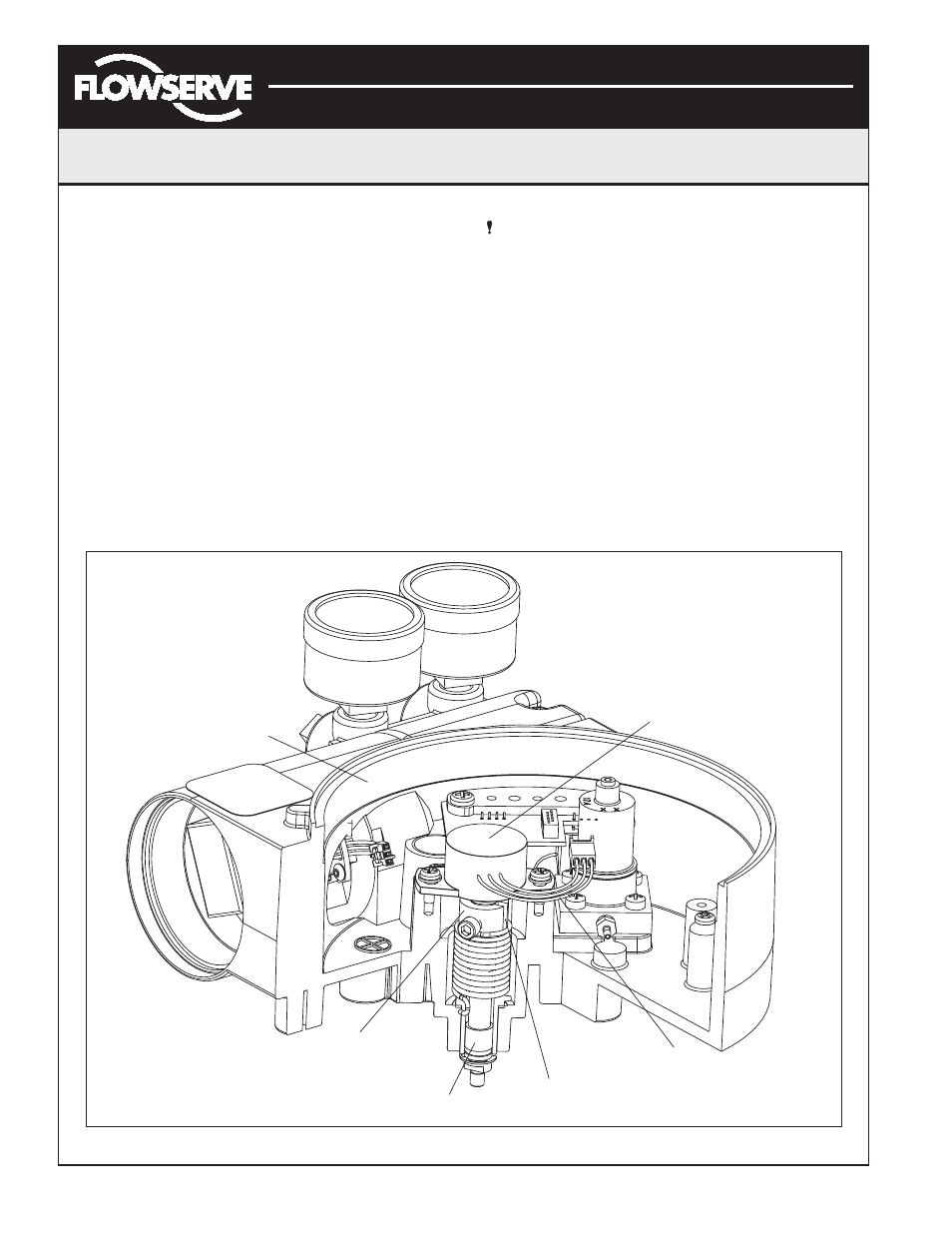
Stem Position
Sensor Dot
Bearing
Feedback
Shaft
Sensor
Cable
Stem
Position
Sensor
Housing
Figure 21: Stem Position Sensor Orientation