Automax logix 3200iq digital positioner, Optional hardware – Flowserve Logix 3200IQ Digital Positioner User Manual
Page 22
Flowserve Corporation
1350 N. Mountain Springs Parkway
1978 Foreman Dr.
Flow Control Division
Springville, Utah 84663-3004
Cookville, TN 38501
www.flowserve.com
Phone: 801 489 2233
Phone: 931 432 4021
FCD AXAIM3200-00 9/04
Page: 22 of 32
© 2004, Flowserve Corporation, Printed in USA
Automax Logix 3200IQ Digital Positioner
Installation, Operation and Maintenance Instructions
14. Install the main PCB into the housing. Insert the
retaining screw through the board into the threaded
boss and tighten evenly, using a Phillips screwdriver.
Do not overtighten.
15. Reinstall the five wire connections (six wire
connections if the unit is equipped with the 4-20 mA
analog output option) on the main PCB assembly (see
Figure 14).
16. Install the plastic board cover. Insert the three retaining
screws through the plastic cover into the threaded boss
and tighten evenly, using a Phillips screwdriver. Do not
overtighten (see Figure 18).
17. Reinstall all covers.
Optional Hardware
Vented Design (See Figures 21 and 23)
A standard Logix 3200IQ positioner is vented directly to
the atmosphere. When supply air is substituted with sweet
natural gas, piping must be used to route the exhausted
natural gas to a safe environment. This piping system may
cause some positioner back pressure in the main chamber
(from the modulator and regulator) and spool chamber
(from the actuator). Back pressure limitations are
described below.
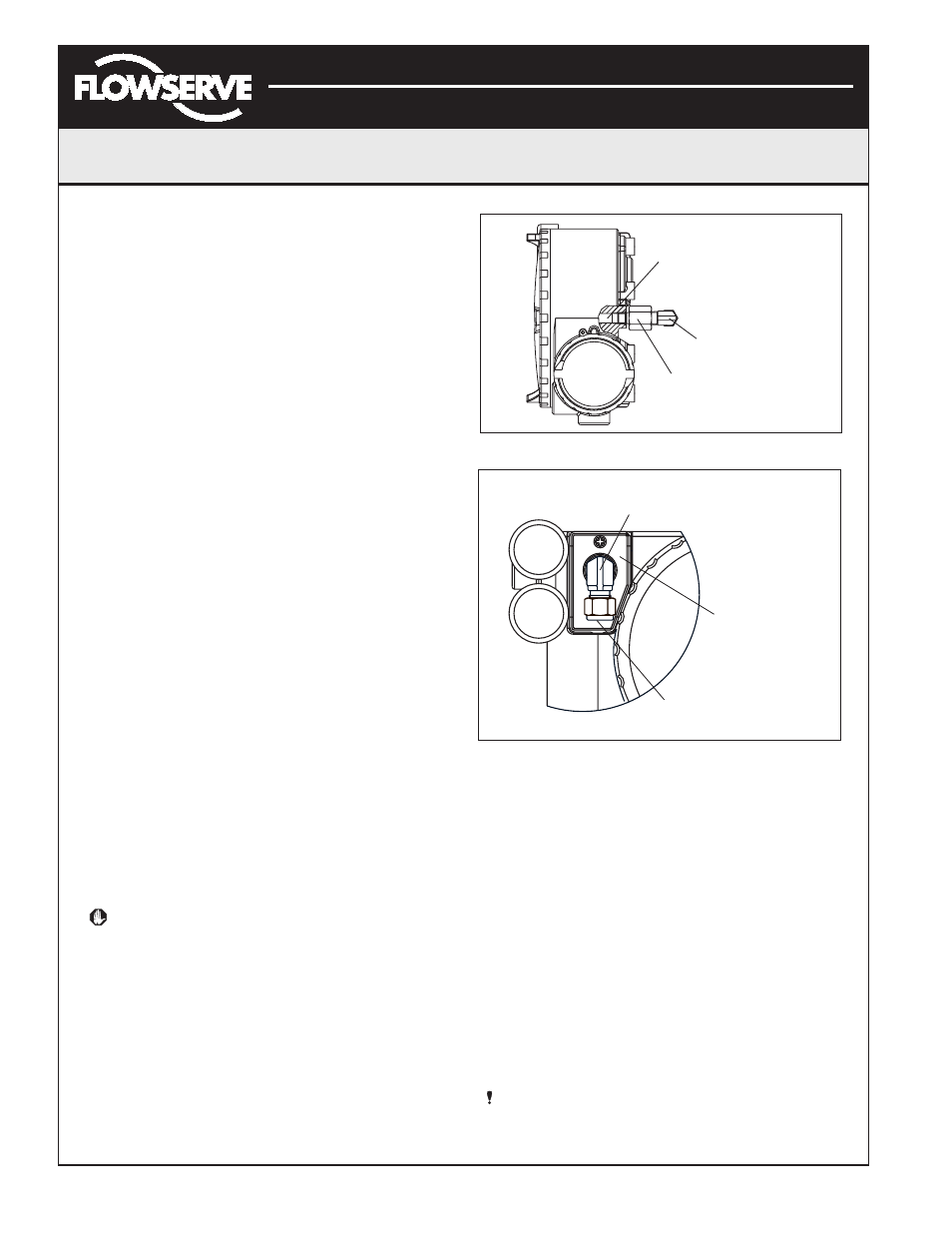
Two chambers must be vented on the Logix 3200IQ
positioners: the main housing chamber and the spool
valve chamber (Figures 21 and 23). The main chamber
vent is located on the backside of the positioner (see
Figure 19). Vented-design Logix 3200IQ positioners are
supplied from the factory with a fitting installed in the
main chamber vent. Connect the necessary tubing/piping
to this fitting to route the exhausted natural gas to a safe
environment.
The maximum allowable back pressure from the collection
device on the main housing vent is 2.0 psig (0.14 barg).
Vent flow rate is 0.5 std ft
3
/min (1.4 std liter/min).
WARNING: The back pressure in the main housing
must never rise above 2.0 psig (0.14 barg).
The spool valve chamber (see Figure 23) must also be
vented through the spool valve cover. Vented-design
Logix 3200IQ positioners are supplied from the factory
with a fitting installed in the spool valve cover (item
SKU 179477). Connect the necessary tubing/piping to
this fitting to route the exhausted natural gas to a safe
environment. The maximum allowable back pressure in
the spool valve chamber is 8 psig (0.55 barg). Pressures
greater than 8 psig will cause vented gas to leak past the
spool cover O-ring to the atmosphere and will result in
overshoot of the positioner.
Figure 22: Main Housing Vent
Figure 23: Spool Cover Vent
HART VHF Filter
HART communication superimposes two frequencies,
1200 Hz and 2200 Hz, on the DC 4-20 mA current signal.
Some current sources (DCS or 4-20 mA calibrator) can
interfere with the HART signal. This may prevent
communication with SoftTools or the HART 275/375
handheld. Intermittent communication may also be the
result of a HART incompatible current source. In this
case, a filter is necessary between the current source and
Logix 3200 to allow HART communication.
Flowserve makes a filter (Part No. 139774) that must be
used on each 4-20 mA line if the current source interferes
with communication (see Figure 24). The filter does not
affect the DC current but prevents the source from
affecting the HART frequencies. The filter comes in a
DIN rail-mount package.
NOTE: This filter is not rated for use in hazardous
areas. It should be located between the current source
and the barrier in intrinsically safe applications.
Maximum Allowable
Housing
Back Pressure
2.0 psig (0.14 barg)
1
/
4
" NPT x
1
/
4
"
Swagelok Tube Fitting
1
/
4
" FNPT x
1
/
8
"
NPT Reducer
Maximum Allowable
Spool Back Pressure
8 psig (0.55 barg)
Customer Connection
Tubing
3
⁄
8
"
NPT x Swagelok
Tube Fitting
3
⁄
8
"
3
⁄
8
"