Automax logix 3200iq digital positioner – Flowserve Logix 3200IQ Digital Positioner User Manual
Page 17
Flowserve Corporation
1350 N. Mountain Springs Parkway
1978 Foreman Dr.
Flow Control Division
Springville, Utah 84663-3004
Cookville, TN 38501
www.flowserve.com
Phone: 801 489 2233
Phone: 931 432 4021
FCD AXAIM3200-00 9/04
Page: 17 of 32
© 2004, Flowserve Corporation, Printed in USA
Automax Logix 3200IQ Digital Positioner
Installation, Operation and Maintenance Instructions
11. Install the main PCB into the housing. Insert the
retaining screw through the board into the threaded
boss and tighten evenly, using a Phillips screwdriver.
Do not overtighten.
12. Reinstall the five wire connections (six wire
connections if the unit is equipped with the 4-20 mA
analog output option).
13. Install the plastic board cover. Insert the three retaining
screws through the plastic cover into the threaded
boss and tighten evenly, using a Phillips screwdriver.
Do not overtighten (see Figure 18).
14. Reinstall all covers.
Checking or Setting Internal Regulator Pressure
To check or set the internal regulator pressure, refer to
Figure 19 and proceed as outlined below. The tools and
equipment used in the next procedure are from indicated
vendors. The following tools are required:
• Calibrated pressure gauge (0 to 30 psi)
• 1⁄ 16" flexible tubing
• Barbed Tee (Clippard Minimatic part number T22-2
or equivalent)
• 3 ⁄ 32" Allen wrench
• 3 ⁄ 8" open-end wrench
WARNING: Observe precautions for handling
electrostatically sensitive devices.
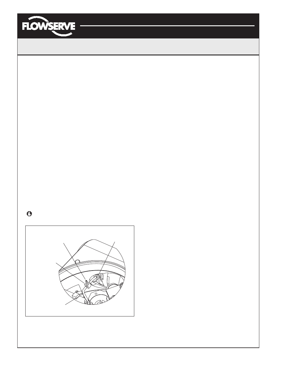
Figure 19: Driver Module Regulator Pressure Check
1. Make sure the valve is bypassed or in a safe condition.
2. Remove the main cover.
3. Remove the plastic board cover by removing the three
retaining screws.
4. Remove the 1⁄ 16" flexible tubing from the barbed
fitting on the side of the driver module.
5. Obtain a barbed tee and two pieces of 1⁄ 16" flexible
tubing, a few inches in length each.
6. Position the barbed tee between the internal regulator
and the driver module by connecting the 1⁄ 16" flexible
tubing, found in the positioner, to one side of the
barbed tee. Using one of the new flexible tubing pieces,
connect the barbed tee to the barbed fitting on the side
of the driver module. Connect the remaining port on
the barbed tee to a 0 to 30 psi pressure gauge.
7. Reconnect the air supply to the positioner and read the
internal regulator pressure on the 0 to 30 psig gauge.
The internal pressure should be set to 17.4 ±0.2 psig.
If adjustment is needed, loosen the set screw retaining
nut on the top of the regulator using the 3 ⁄ 8" open-end
wrench. Then adjust the regulator pressure by turning
the set screw on the top of the regulator with the 3 ⁄ 32"
Allen wrench.
8. Once the regulator pressure is set, tighten the set
screw retaining nut on the top of the regulator, remove
the air supply to the positioner, remove the barbed tee,
and reconnect the flexible tubing from the regulator to
the barbed fitting on the side of the driver module.
9. Install the plastic board cover. Insert the three retaining
screws through the plastic cover into the threaded
boss and tighten evenly, using a Phillips screwdriver.
Do not overtighten (see Figure 18).
10. Reinstall all covers.
Spool Valve
The spool valve routes the supply air to one side of the
actuator while venting the opposite side (see Figure 2).
The position of the spool valve is controlled by the
driver module.
Replacing the Spool Valve
To replace the spool valve, refer to Figures 15, 17 and 28
and proceed as outlined below. The following tools are
required:
• Phillips screwdriver
1. Make sure the valve is bypassed or in a safe condition.
2. Disconnect the power and air supply to the unit.
3. Remove the spool valve cover by removing the screw
and sliding the cover assembly backwards until the tab
Regulator Pressure
Test Port
Barbed Tee
(Clippard Minimatic
Part No. T22-2)
Flexible Tube
from Regulator
Driver Module
Barbed Fitting
10-32 x
1
/
16
"