Automax logix 3200iq digital positioner – Flowserve Logix 3200IQ Digital Positioner User Manual
Page 23
Flowserve Corporation
1350 N. Mountain Springs Parkway
1978 Foreman Dr.
Flow Control Division
Springville, Utah 84663-3004
Cookville, TN 38501
www.flowserve.com
Phone: 801 489 2233
Phone: 931 432 4021
FCD AXAIM3200-00 9/04
Page: 23 of 32
© 2004, Flowserve Corporation, Printed in USA
Automax Logix 3200IQ Digital Positioner
Installation, Operation and Maintenance Instructions
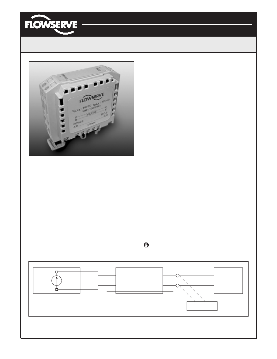
Figure 24: HART VHF Filter
HART Modem
The HART modem is a device that connects to the
serial communications port of a computer. This modem
converts the RS-232 COM port signals to the HART
signal. A HART modem is optional in SoftTools since a
MUX can be used in its place. The HART modem takes
power from the RS-232 COM port lines. If using a
laptop computer running on an internal battery, HART
communication may become erratic as the batteries
begin to lose charge. This is due to a reduction in HART
modem power. Allow batteries to recharge or apply AC
adapter power to the laptop to correct the problem.
A HART modem is available through your Flowserve
representative. (Please refer to Logix 3200IQ Spare
Parts Kit Section for part numbers.)
When using a HART modem with SoftTools or when using
the HART 275/375 handheld, the leads can be connected
anywhere across the 4-20 mA current signal. The leads
are not polarity sensitive. When using a filter, the
connection must be made between the filter output and
the Logix 3200IQ (see Figure 25).
4-20 mA Analog Output Board
The Logix 3200IQ digital positioner can be supplied to
provide an analog feedback signal of the stem position.
This option can also be retrofitted in the field. The 4-20
mA analog output board is wired in series with a 12.5 to
40 VDC power supply (see Figure 26). This position
feedback option has the following features and
specifications:
• Does not interfere with positioner operation.
• Calibration of the analog output signal is performed
using a HART 275/375 Handheld Communicator or
configuration software such as SoftTools.
• Output follows actual position of valve, including all
failure modes of positioner except loss of power. An
output of
≤
3.15 mA is transmitted with loss of power
to the positioner.
• Immune to RFI/EMI disturbances.
• Available for explosion-proof and safe applications
(CSA, FM).
Replacing the 4-20 mA Analog Output Board
To replace the 4-20 mA analog output board, refer to
Figures 14, 18 and 28 and proceed as outlined below.
The following tools are required:
• Phillips screwdriver
WARNING: Observe precautions for handling
electrostatically sensitive devices.
Figure 25: HART VHF Filter Schematic
+
–
+
–
+
–
C
D
F
E
G, H
A, B
DCS
LOGIX
HART Connection
FILTER
Drain Wire
4-20 mA
Current Source
Logix
3200IQ