Automax logix 3200iq digital positioner – Flowserve Logix 3200IQ Digital Positioner User Manual
Page 24
Flowserve Corporation
1350 N. Mountain Springs Parkway
1978 Foreman Dr.
Flow Control Division
Springville, Utah 84663-3004
Cookville, TN 38501
www.flowserve.com
Phone: 801 489 2233
Phone: 931 432 4021
FCD AXAIM3200-00 9/04
Page: 24 of 32
© 2004, Flowserve Corporation, Printed in USA
Automax Logix 3200IQ Digital Positioner
Installation, Operation and Maintenance Instructions
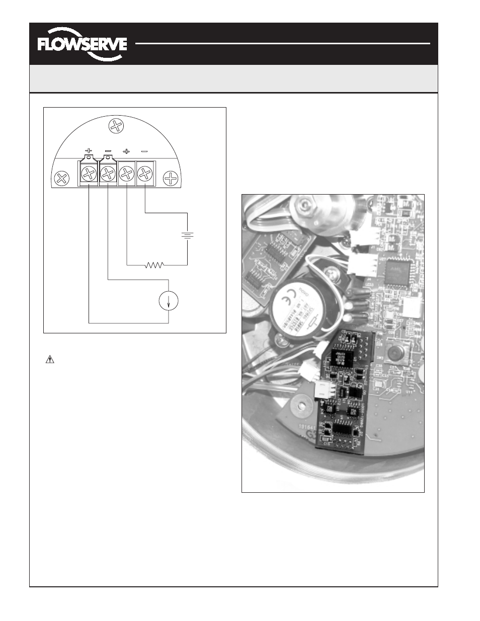
Figure 26: Analog Output Board Power
CAUTION: Isolated power sources required.
1. Make sure the valve is bypassed or in a safe condition.
2. Disconnect the power and air supply to the unit.
3. Remove the main cover.
4. Remove the plastic board cover by removing the three
retaining screws (see Figure 18).
5. Disconnect the two wire connection from the side of
the 4-20 mA analog output board.
6. Gently lift the 4-20 mA analog output board off the
main PCB assembly.
7. Align the two connectors on the new 4-20 mA analog
output board with the mating sockets on the main PCB
board and gently press the connectors together.
8. Connect the two wire connection coming from the User
Interface board to the side of the 4-20 mA analog
output board.
9. Install the plastic board cover. Insert the three retaining
screws through the plastic cover into the threaded
boss and tighten evenly, using a Phillips screwdriver.
Do not overtighten.
10. Connect the Analog Output filed termination wiring to
the Analog Output terminals on the User Interface
board (see Figure 26.)
11. Reinstall all covers.
Figure 27: 4-20 mA Analog Output Board
HART
4-20 mA
ANALOG
INPUT
OUTPUT
Position Feedback
Current Loop
(Logix Output)
Position Command
Current Loop
(Logix Input)
12 VDC
to 40 VDC
Power
Supply
4 to 20 mA
Current Source
+
+
–
–