Automax logix 3200iq digital positioner – Flowserve Logix 3200IQ Digital Positioner User Manual
Page 9
Flowserve Corporation
1350 N. Mountain Springs Parkway
1978 Foreman Dr.
Flow Control Division
Springville, Utah 84663-3004
Cookville, TN 38501
www.flowserve.com
Phone: 801 489 2233
Phone: 931 432 4021
FCD AXAIM3200-00 9/04
Page: 9 of 32
© 2004, Flowserve Corporation, Printed in USA
Automax Logix 3200IQ Digital Positioner
Installation, Operation and Maintenance Instructions
Description of Configuration DIP Switch Settings
The first seven DIP switches are for basic configuration.
The function of each switch is described below.
Air Action
This must be set to match the configuration of the
valve/actuator mechanical tubing connection and spring
location since these determine the air action of the
system.
ATO (air-to-open) – Selecting ATO if increasing output
pressure from the positioner is tubed so it will cause the
valve to open.
ATC (air-to-close) – Selecting ATC if increasing output
pressure from the positioner is tubed so it will cause the
valve to close.
Signal at Closed
Normally this will be set to 4 mA for an Air-to-open
actuator and 20 mA for an Air-to-close actuator
configuration.
4 mA – Selecting 4 mA will make the valve fully closed
when the signal is 4 mA and fully open when the signal
is 20 mA.
20 mA – Selecting 20 mA will make the valve fully
closed when the signal is 20 mA and fully open when
the signal is 4 mA.
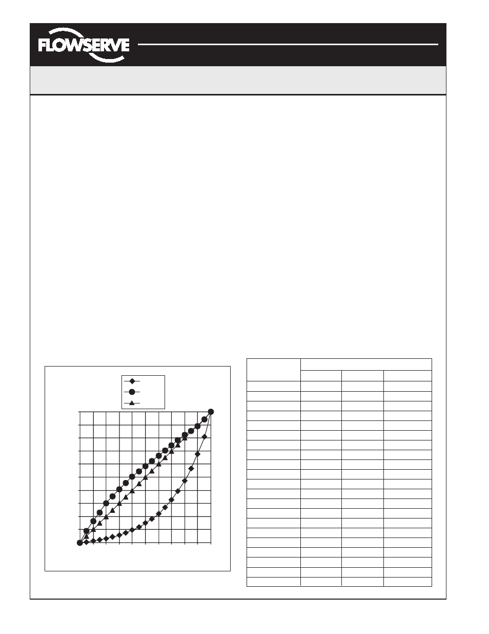
Figure 12: Default Custom Characterization
Pos. Characterization
Linear – Select Linear if the actuator position should be
directly proportional to the input signal.
Optional – Select Optional if another characteristic is
desired, which is set in conjunction with the next switch,
labeled Optional Pos. Char.
Optional Pos. Characterization
If the Pos. Characterization switch is set to optional then
this switch is active with the following options:
=% – The =% option will characterize the actuator
response to the input signal based on a standard 30:1
equal percent rangeability curve.
Custom – If Custom is selected, the positioner will be
characterized to a custom table that must be set-up
using a properly configured HART 275/375 handheld or
other host software. Custom characterization can be
thought of as a “soft CAM.” The user can define a
characterization curve using 21 points. The control will
linearly interpolate between points. Points do not have
to be equally spaced in order to allow more definition at
critical curve areas. The default values will linearize the
output of a valve with an inherent =% characteristic
(e.g., ball valves).
Table VIII: Characteristic Curve Data
% Command
% Control Command
=%
Linear
Custom
0
0
0
0
5
0.62
5
8.66
10
1.35
10
16.24
15
2.22
15
23.17
20
3.25
20
30.11
25
4.47
25
35.31
30
5.91
30
40.51
35
7.63
35
45.42
40
9.66
40
50.34
45
12.07
45
54.40
50
14.92
50
58.47
55
18.31
55
62.39
60
22.32
60
66.31
65
27.08
65
70.27
70
32.71
70
74.23
75
39.40
75
78.17
80
47.32
80
82.11
85
56.71
85
85.50
90
67.84
90
88.89
95
81.03
95
94.45
100
100.00
100
100.00
0
10
20
30
40
50
60
70
80
90 100
=%
Custom
Linear
0
10
20
30
40
50
60
70
80
90
100
% Control Command
% Command