Automax logix 3200iq digital positioner, Wiring and grounding guidelines – Flowserve Logix 3200IQ Digital Positioner User Manual
Page 6
Flowserve Corporation
1350 N. Mountain Springs Parkway
1978 Foreman Dr.
Flow Control Division
Springville, Utah 84663-3004
Cookville, TN 38501
www.flowserve.com
Phone: 801 489 2233
Phone: 931 432 4021
FCD AXAIM3200-00 9/04
Page: 6 of 32
© 2004, Flowserve Corporation, Printed in USA
Automax Logix 3200IQ Digital Positioner
Installation, Operation and Maintenance Instructions
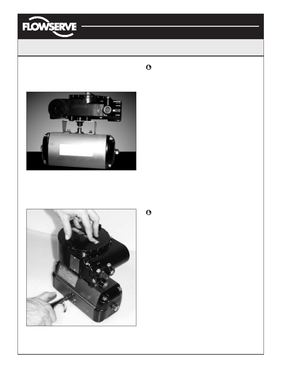
5. Making sure positioner shaft rotation matches actuator
shaft rotation, place positioner on mounting bracket
(Figure 7). Make sure shafts engage. Do not insert
fasteners into positioner at this time.
Figure 7: Positioner on Mounting Bracket
6. Double-check actuator and positioner rotation. Hold
positioner against bracket with fingertips as shown in
Figure 8.
Figure 8: Check Positioner Shaft Alignment
WARNING: Keep away from positioner sides, as
positioner will suddenly rotate on bracket if not
properly aligned and cause injury.
Slowly rotate the actuator. If the positioner shaft is
properly aligned, the shaft will rotate freely. If not, the
mechanical stops will grab, causing the positioner body
to rotate on bracket.
7. If the shaft is not properly aligned, repeat steps 3-6.
Otherwise, attach positioner to bracket with fasteners
included with bracket. Tighten bolts finger-tight only at
this time.
8. Stroke actuator/positioner several times to align shafts.
Tighten all fasteners.
Tubing Positioner to Actuator
Proper tubing orientation is critical for the positioner to
function correctly and have the proper failure mode. Referring
to Figure 2, note that for air-to-open valves, the Output 1 port
of the positioner manifold is tubed to the ‘open’ side of the
actuator. The Output 2 port of the positioner manifold is tubed
to the ‘closed’ side of the actuator. For air-to-close valves the
above configuration is reversed.
Wiring and Grounding Guidelines
(See Figure 9)
WARNING: This product has electrical conduit
connections in either thread sizes 1/2" NPT or M20
which appear identical but are not interchangeable.
Housings with M20 threads are stamped with the
letters M20 above the conduit opening. Forcing
dissimilar threads together will damage equipment,
cause personal injury and void hazardous location
certifications. Conduit fittings must match
equipment housing threads before installation.
If threads do not match, obtain suitable adapters
or contact a Flowserve representative.
4-20 mA Command Input Wiring
Verify polarity when making field termination connection.
The Logix 3200 is reverse polarity protected. Wire 4-20
mA current source to the input terminal labeled 4-20 mA
Input on the user interface board (see Figure 9). Never
connect a voltage source directly across the Logix 3200IQ
terminals. The current must always be limited for 4-20
mA operation. Minimum operating current is 3.6 mA.
The input loop current signal to the Logix 3200IQ digital
positioner should be in shielded cable. Shields must be
tied to a ground at only one end of the cable to provide
a place for environmental electrical noise to be removed
from the cable. In general, shield wire should be
connected at the source.