Automax logix 3200iq digital positioner – Flowserve Logix 3200IQ Digital Positioner User Manual
Page 18
Flowserve Corporation
1350 N. Mountain Springs Parkway
1978 Foreman Dr.
Flow Control Division
Springville, Utah 84663-3004
Cookville, TN 38501
www.flowserve.com
Phone: 801 489 2233
Phone: 931 432 4021
FCD AXAIM3200-00 9/04
Page: 18 of 32
© 2004, Flowserve Corporation, Printed in USA
Automax Logix 3200IQ Digital Positioner
Installation, Operation and Maintenance Instructions
is clear of the slot. It is not necessary to remove the
sheet metal cap, hydrophobic filter, or O-ring from this
assembly (Figure 17).
WARNING: The spool (extending from the driver
module assembly) is easily damaged. Use extreme
caution when handling spool and spool valve block.
Do not handle the spool by the machined portions of
spool. The tolerances between the block and spool
are extremely tight. Contamination in the block or on
the spool may cause the spool to hang.
4. Remove the spool valve block by removing the two
Phillips-head screws and carefully sliding the block off
the spool (Figure 15).
5. Carefully remove spool by sliding end of spool out of
connecting clip. Excessive force may bend the spool.
6. Verify that the three O-rings are in the counterbores on
the machined platform where the new spool valve
block is to be placed (Figure 28).
7. Carefully slide the spool into the connecting clip of the
driver module assembly.
8. Carefully slide the block over the spool, using the
machined surface of the housing base as a register
(Figure 15). Slide the block toward the driver module
until the two retaining holes line up with the threaded
holes in the base.
9. Install two spool valve screws and tighten securely
with a Phillips screwdriver (see Figure 16).
10. Slide the spool valve cover assembly over the spool
valve until the tang engages into the housing slot.
Install the spool valve cover screw and tighten securely
(see Figure 15).
11. Reconnect power and air supply to the positioner and
perform a stroke calibration.
Spool Valve Cover
The spool valve cover incorporates a coalescing filter
element in a two-piece cover. This protects the spool
valve chamber from dirt and moisture and provides a low
back pressure vent for exhaust air from the spool valve.
Replacing Filter in Spool Valve Cover
To replace the filter in the spool valve cover, refer to
Figures 15 and 20 and proceed as outlined below.
The following tools are required:
• Phillips screwdriver
1. Remove the spool cover by removing the screw and
sliding the cover assembly backwards until the tab
is clear of the slot. The sheet metal cover may be
removed and cleaned with a brush or by blowing
out with compressed air (Figure 15).
2. Remove the O-ring from around the hydrophobic filter
element and set aside (Figure 20).
3. Remove the molded filter element by pulling it straight
out of the chamber cover vent piece.
4. Install O-ring into base of chamber cover vent piece as
shown in Figure 20.
5. Place new molded filter element into the chamber
cover vent piece. This filter element provides part of
the track to secure the O-ring installed in the last step.
6. Place spool valve shroud onto spool valve cover.
7. Place the spool valve cover assembly in place by
setting it on the ramp and sliding it until the tab seats
in the slot (Figures 15 and 20) and secure with a
8-32 screw.
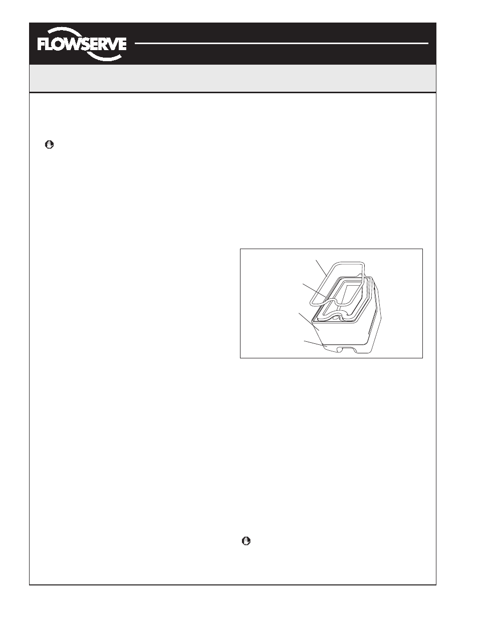
Figure 20: Spool Valve Cover Assembly
Stem Position Sensor
The position feedback assembly transmits valve positions
information to the processor. This is accomplished by
means of a rotary position sensor that connects to the
valve stem through a feedback linkage. To provide for
accurate tracking of the pin in the slot, the follower arm is
biased against one side of the slot with a rotary spring.
This spring also automatically moves the position
feedback assembly to its limit in the unlikely event of
failure of any component in the linkage.
Stem Position Sensor Replacement
To replace the stem position sensor, refer to Figure 18, 21
and 28 and proceed as outlined below. The following tools
are required:
• Phillips screwdriver
WARNING: Observe precautions for handling
electrostatically sensitive devices.
1. Make sure the valve is bypassed or in a safe condition.
2. Disconnect the power and air supply to the unit.
O-ring
Hydrophobic
Filter
Spool
Valve
Cover
Spool
Valve Shroud