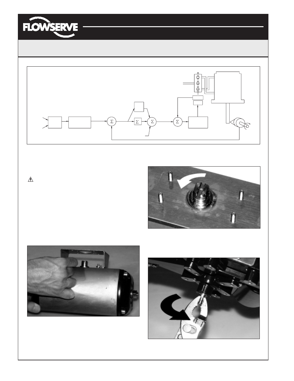
Automax logix 3200iq digital positioner, Figure 3: system positioning algorithm – Flowserve Logix 3200IQ Digital Positioner User Manual
Page 5
Flowserve Corporation
1350 N. Mountain Springs Parkway
1978 Foreman Dr.
Flow Control Division
Springville, Utah 84663-3004
Cookville, TN 38501
www.flowserve.com
Phone: 801 489 2233
Phone: 931 432 4021
FCD AXAIM3200-00 9/04
Page: 5 of 32
© 2004, Flowserve Corporation, Printed in USA
Automax Logix 3200IQ Digital Positioner
Installation, Operation and Maintenance Instructions
Mounting the Positioner
CAUTION: Positioner shaft is spring-loaded and
features mechanical stops at each end of stroke.
Failure to follow these procedures carefully may
result in severe damage to positioner. Read through
entire procedure before starting.
1. Attach positioner mounting bracket to actuator using
fasteners supplied with bracket (Figure 4). Tighten
bolts finger-tight only at this time.
2. Install coupler (if required – coupler is not required
for NAMUR mounting) on actuator shaft, making sure
it is centered.
Figure 4: Linear Mark One Control Valve Mounting
3. Stroke the actuator to determine direction of rotation
as shown in Figure 5. Pay specific attention to the slot
that will engage positioner shaft.
Figure 5: Actuator Shaft
4. Carefully grasp positioner shaft with pliers as shown in
Figure 6. Turn shaft to determine direction of rotation.
Figure 6: Turn Positioner Shaft
Sensor
–
+
+
+
+
Summer
Integration
I
Offset
Loop
Inner
+
–
Gmult
Pmin
Pmax
Deviation
4-20 mA
(Analog
Mode)
Command In
(Digital
Mode)
Signal
Input
Digital
Analog
CONTROL
COMMAND
Output
D/A
Percentage
Algorithm
Control
Supply
Air
Control
Spool
Loop
Inner
ATO
Tubed
Sensor
Position
Stem
Voltage
Valve
Piezo
MPC
Soft Limits
Characterization
Linear Mode
Output
Inner-Loop
Figure 3: System Positioning Algorithm