Radio connector (j2), Input/output radio connector table – GAI-Tronics ITA2000A ITA2000A Series Tone Remote Adapter with Scanning User and Installation Manual User Manual
Page 21
ITA2000A Series Tone Remote Adapter
Installation
17
03/13
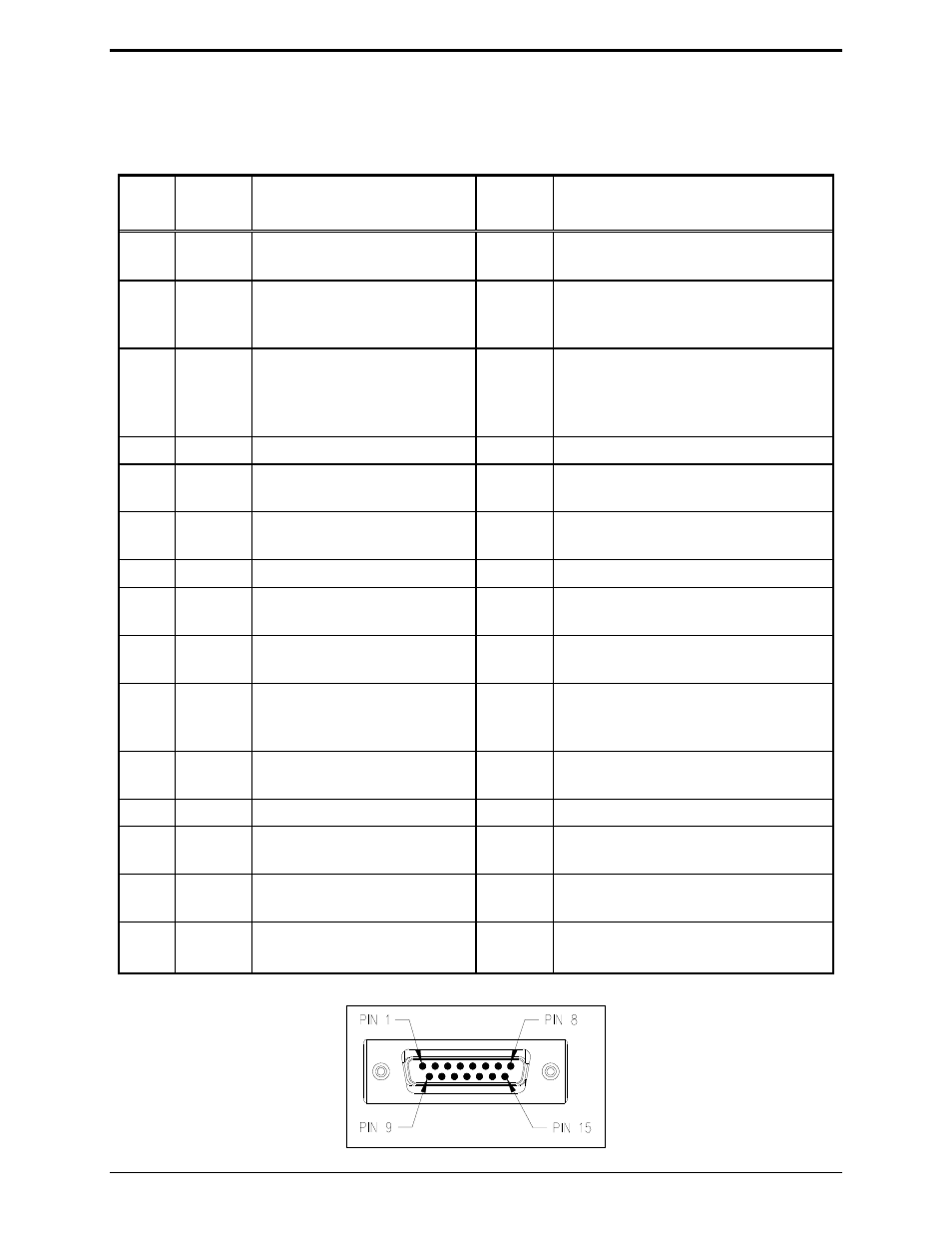
Radio Connector (J2)
The radio connector is located on the rear of the ITA2000A. The connector pinout appears below:
Input/Output Radio Connector Table
Pin
Wire
Color
Description
Input/
Output
Range
J2-1 Black/
white
Channel Steer 3
O
JU4 B position = Lo (0 V dc)*
JU4 A position = Hi (B+)
J2-2 Blue/
white
CSQ Detect (SW1-1 must be
Down) Refer to Switch
Table.
I
SW1-2 UP = Lo (0 V dc)*
SW1-2 DOWN = Hi (B+)
J2-3
Green
RX Audio + (Selectable)
300 mV
RMS
nominal/default
I
Range 1: −20 dB Jumper = OUT
32 mV
RMS
–1.6 V
RMS
Range 2: −20 dB Jumper = IN
1.5 V
RMS
–4.5 V
RMS
J2-4 Black AGND
J2-5 White/
black
Channel Steer 2
O
JU5 B position = Lo (0 V dc)*
JU5 A position = Hi (B+)
J2-6
White
PTT
O
JU2 B position = Lo (0 V dc)*
JU2 A position = Hi (B+)
J2-7
Orange
RX PL Disable
O
Closure between pins 7 and 14
J2-8
Red
Channel Steer 0
O
JU7 B position = Lo (0 V dc)*
JU7 A position = Hi (B+)
J2-9 Red/
white
Channel Steer 4
O
JU3 B position = Lo (0 V dc)*
JU3 A position = Hi (B+)
J2-10 Green/
white
CSQ and CTCSS Detect
(SW1-1 must be Down.)
Refer to Switch Table.
I
SW1-2 UP = Lo (0 V dc)*
SW1-2 DOWN = Hi (B+)
J2-11 Green/
Black
RX Audio – (AGND)
I
Connected internally to pin 4 at radio
end of cable.
J2-12 Blue
TX Audio
O
32 mV
RMS
–800 mV
RMS
560 ohms
J2-13 Blue/
black
PTT Sense
I
SW1-3 UP = Lo (0 V dc)*
SW1-3 DOWN = Hi (B+)
J2-14 Orange/
black
RX PL Disable
O
Closure between pins 7 and 14
J2-15 Red/
black
Channel Steer 1
O
JU6 B position = Lo (0 V dc)*
JU6 A position = Hi (B+)
*default from the factory
Radio Connector Pinout