Channel select pin designation/output chart – GAI-Tronics ITA2000A ITA2000A Series Tone Remote Adapter with Scanning User and Installation Manual User Manual
Page 23
ITA2000A Series Tone Remote Adapter
Installation
19
03/13
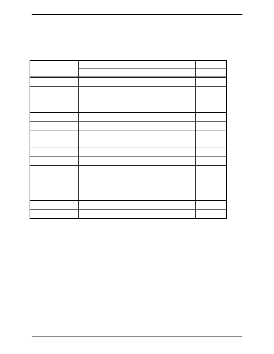
These pins output the binary equivalent of the decoded function tone from the tone remote or the current
scan selected channel. The chart that follows shows the pin designation and output for the decoded
function tone. These outputs can be used to control other logic-driven functions of radios that support
such features.
Channel Select Pin Designation/Output Chart
Pin 9
Pin 1
Pin 5
Pin 15
Pin 8
F#
Frequency
MSB
Bit 3
Bit 2
Bit 1
LSB
F1
1950 Hz
High
High High High Low
F2
1850 Hz
High
High High Low High
F3
1750 Hz
High
High High Low Low
F4
1650 Hz
High
High Low High High
F5
1550 Hz
High
High Low High Low
F6
1450 Hz
High
High Low Low High
F7
1350 Hz
High
High
Low
Low
Low
F8
1250 Hz
High
Low High High High
F9
1150 Hz
High
Low High High Low
F10 1050 Hz
High
Low High Low High
F11 950 Hz
High
Low
High
Low
Low
F12 850 Hz
High
Low Low High High
F13 750 Hz
High
Low
Low
High
Low
F14 650 Hz
High
Low
Low
Low
High
F15 550 Hz
High
Low
Low
Low
Low
F16* 2050
Hz
Low
High
High High High
*F16 is switch selectable between a monitor and channel steer function (Conventional) or scan on/off
function (Scan).
N
OTE
: The logic is inverted if the ITA2000A channel selection outputs are set for active high.
If programmable or N/C pins are not used, clip off or secure in a fashion to prevent leads from
shorting together, thus preventing damage to the adapter or the radio.