Ita2000a to rpg radio connection chart – GAI-Tronics ITA2000A ITA2000A Series Tone Remote Adapter with Scanning User and Installation Manual User Manual
Page 27
ITA2000A Series Tone Remote Adapter
Installation
23
03/13
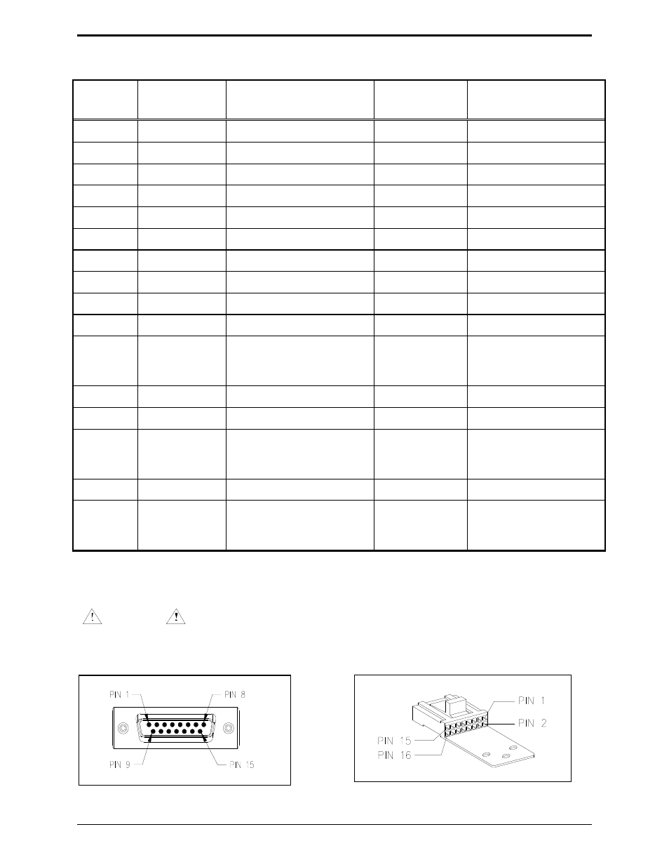
ITA2000A to RPG Radio Connection Chart
Adapter
Pin
Adapter
Function
Wire Color
Radio
Connector Pin
Radio Function
1
Channel steer 3 Black w/white stripe
6, 8, 9, 12, or 14 Programmable
2
CSQ Detect IN Blue w/white stripe
4, 8, 12, or 14
Programmable
3
RX audio +
Green
11
RX audio
4 AGND
Black
7
GND
5
Channel steer 2 White w/black stripe
6, 8, 9, 12, or 14 Programmable
6 PTT
White
3
Mic
PTT
7
Monitor
Orange
14, or 6, 8, 9, 12 PL disable (monitor)
8
Channel steer 0 Red
6, 8, 9, 12, or 14 Programmable
9
Channel steer 4 Red w/white stripe
6, 8, 9, 12, or 14 Programmable
10
CTCSS IN
Green w/white stripe
4, 8, 12, or 14
Programmable
11 RX
audio
−
Connected internally to
15D pin 4 at radio end of
cable.
12
TX audio +
Blue
2
Mic audio
13
PTT Sense IN
Blue w/black stripe
N/C
14
Monitor low
Connected internally to
15D pin 4 at radio end of
cable.
15
Channel steer 1 Red w/black stripe
6, 8, 9, 12, or 14 Programmable
Connector
Housing
Shield
Connected internally to
15D pin 4 at radio end of
cable.
N
OTE
: The radio must be programmed to disable emergency functions from pin 9.
RPG includes: DESKTRAC, GM300, M1225 (four-channel only).
WARNING
If programmable or N/C pins are not used, clip off or secure in a fashion to prevent leads from
shorting together, thus preventing damage to the adapter or the radio.
Adapter Radio Connector
Radio Connector