GAI-Tronics ITA2000A ITA2000A Series Tone Remote Adapter with Scanning User and Installation Manual User Manual
Page 28
Installation
ITA2000A Series Tone Remote Adapter
03/13 24
ITA2000A Tone Remote Adapter to MCS2000 Radio Connection Chart (Conventional Mode
Only)
15-Pin
Pin #
Adapter
Function
Wire Color
Radio
Connector Pin #
Radio Function
1
Channel Steer 3 Black w/white stripe
N/C
Programmable
2
CSQ Detect IN
Blue w/white stripe
8
Programmable
3
RX audio +
Green
11
RX audio
4 AGND
Black
10
GND
5
Channel Steer 2 White w/black stripe
N/C
Programmable
6 PTT
White
21
Mic
PTT
7 Monitor
Orange
7
CTCSS
disable
(monitor)
8
Channel Steer 0 Red N/C
Programmable
9
Channel Steer 4 Red w/white stripe
N/C
Programmable
10
CTCSS IN
Green w/white stripe
8
Programmable
11
RX audio –
Connected internally to 15D
pin 4 at radio end of cable.
12
TX audio +
Blue
23
Mic audio
13
14 Monitor
low Connected internally to 15D
pin 4 at radio end of cable.
15
Channel Steer 1 Red w/black stripe
N/C
Programmable
Connector
Housing
Shield
Connected internally to 15D
pin 4 at radio end of cable.
WARNING
If programmable or N/C pins are not used, clip off or secure in a fashion to prevent leads from
shorting together, thus preventing damage to the adapter or the radio.
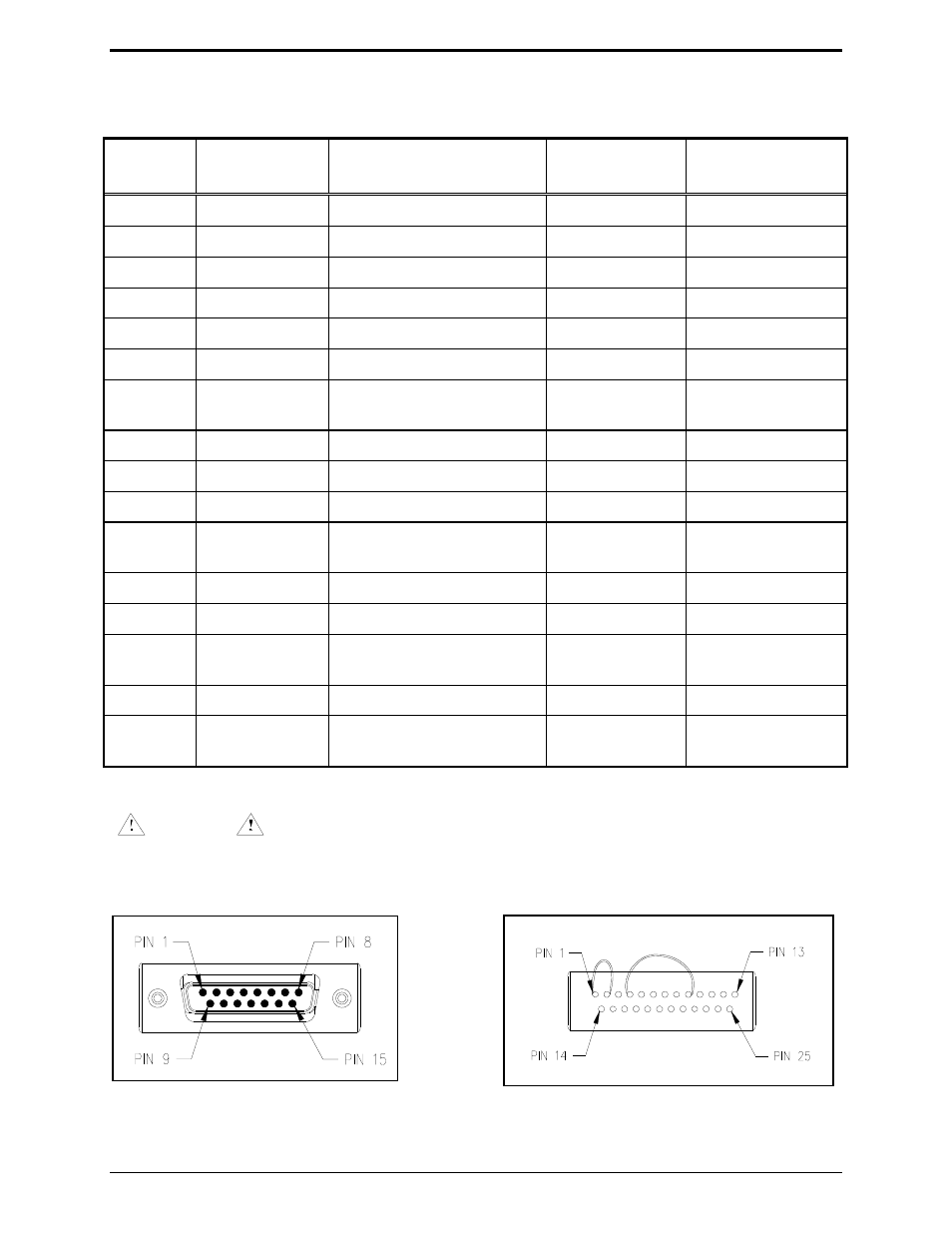
Adapter Radio Connector
HLN6412 Connector Termination with Internal
Jumpers Connecting Pins 1–2 and Pins 4–9.