Hardware configuration, Audio line termination jumper, Fuses – GAI-Tronics 13363 Addressable Amplified Speakers Installation and Operation Manual User Manual
Page 49
Pub. 43004-034F
Model 13353, 13363, and 13373 Addressable Amplified Speakers
Page 44 of 52
e:\radio products-current release\43004\43004-034f\43004-034f.doc
03/15
Hardware Configuration
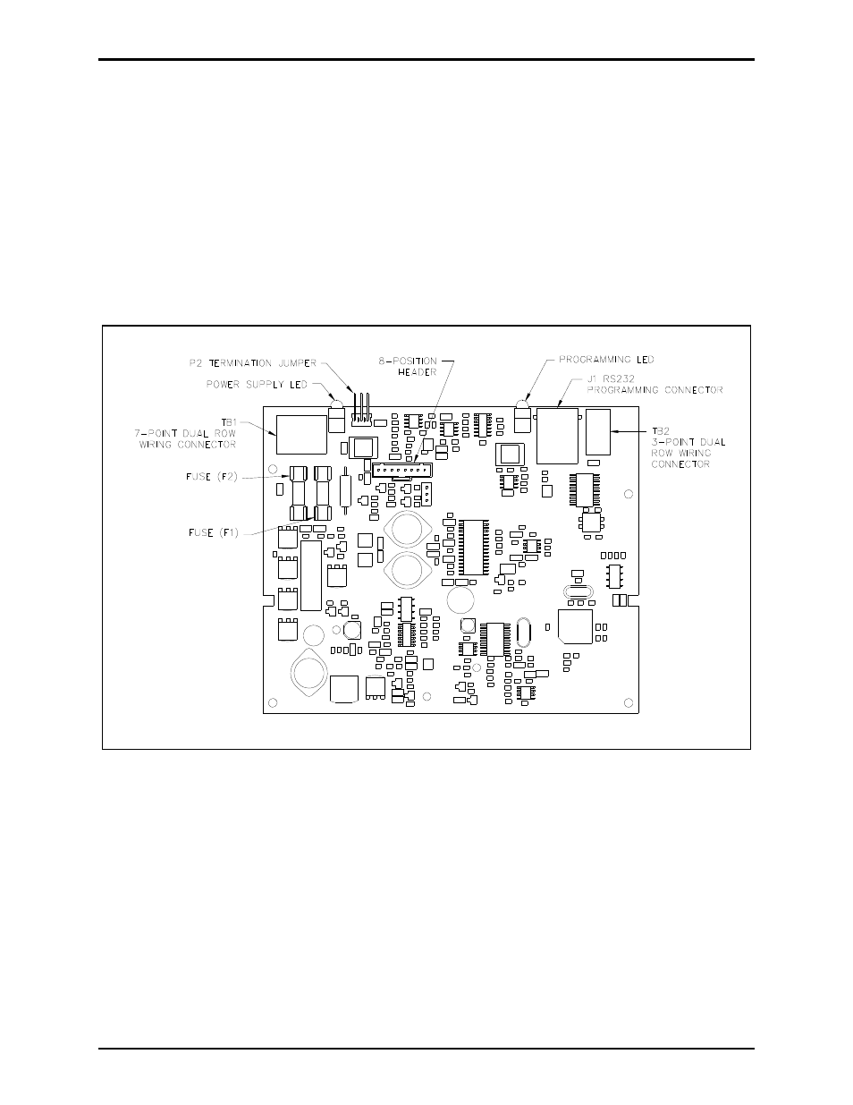
Audio Line Termination Jumper
For hardwired installations the Addressable Amplified Speaker’s circuit board contains a jumper to
terminate the audio line to maintain an appropriate balance. Jumper P2 on the speaker amplifier PCBA
configures the unit for 600-ohm or 15k-ohm line termination. Shorting P2 pins 1 and 2 sets the line
termination to 15k ohms (default setting). Shorting pins 2 and 3 (P2) sets the line termination to 600
ohms. The settings options are labeled next to the jumper on the PCBA. This jumper is accessible by
separating the rear section of the speaker from the front section. Refer to Figure 18 for location of P2.
This jumper has no function in an RF operation.
Figure 18. Amplified Speaker Assembly PCBA (Model 69834)
Fuses
There are two fuses (F1 and F2) located on the speaker amplifier PCBA.
Fuse F1 is a 3-amp fuse that limits the current draw from the 15 V dc power supply. Replace F1 with
Littelfuse (3 amp) 5 × 20 mm or Cooper Bussman (3 amp) 5 × 20 mm fuses only.
Fuse F2 is a 5-amp fuse that limits the current draw from the 15 V dc battery. Replace F2 with Littelfuse
(5 amp) 5 × 20 mm or Cooper Bussman (5 amp) 5 × 20 mm fuses only.