Gasboy Enhanced Communications User Manual
Page 45
MDE-4520C Enhanced Communications Installation Manual · February 2008
Page 45
Serial-to-LAN Connection Installation
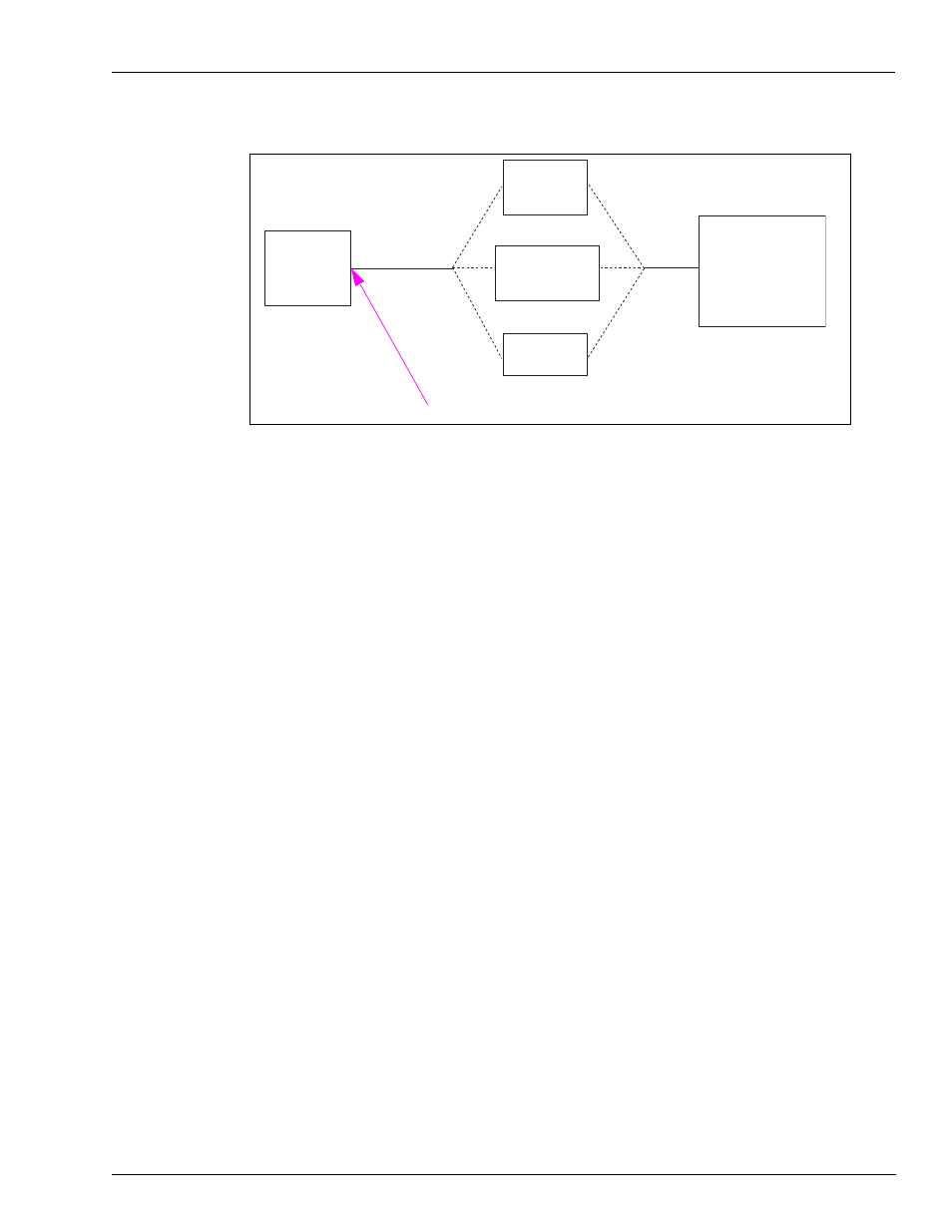
Figure 30: Test PC to Gasboy System Connections
SHM
C05618
Gasboy
Termination Box
Gasboy
D-Type
Connector
Gasboy System
C05769
OR
OR
Test PC
Q13240-09
Serial Port
3
Disconnect the 9 to 25 modem cable from the SHM or termination box or D-type connector
and connect it to one of the serial to LAN adapters.
4
Using a terminal session (for example, HyperTerminal) with settings 9600, 8, N, 1, verify the
adapter is set up as described in
Settings for the Adapter Connected to the Gasboy System
on
. Verify the IP address and port number are set to the values supplied by the Network
Administrator (or other IT personnel). If they are not supplied, use a temporary value of IP
address 192.168.1.101 and port 1001. Also, verify the baud rate matches the Gasboy system.
Close the terminal session. Mark this adapter Gasboy FMS.
5
Disconnect the modem cable from the adapter. Connect the adapter to a C04532 (use the cable
supplied with the kit, if possible). Connect the other end of the C04532 to the SHM or
termination box that was tested in step
above. If you are using a D-type connector (see
), connect it to the serial to LAN adapter.
6
Using the CAT-5 cross cable, connect to the RJ45 jack on the adapter. Connect the other end to
the Ethernet port on the test PC. Ensure that the test PC IP address is not the same the address
configured in the adapter.