7 installation, 1 settings in the terminal cap, 1 participant address – ifm electronic RN3001 User Manual
Page 7: 2 bus termination, Encoder with profibus interface 7, Supply +u
UK
Encoder with Profibus interface
7
7 Installation
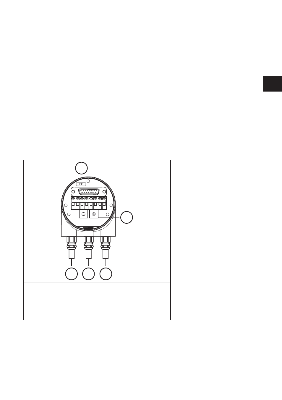
The encoder is connected via the terminal cap� It is connected to the encoder via
a 15-pole D-Sub-connector and can be removed by loosening the 2 screws on the
back of the device� Bus and supply cables are inserted in the cab via cable glands
and connected via screw terminals�
7.1 Settings in the terminal cap
7.1.1 Participant address
The Profibus participant address is set via decimal rotary switches in the terminal
cap� The positional value (x 10 or x 1) is indicated on the switch� Possible
addresses are between 1 and 99; each address must only occur in the system
once�
The device address is read when the voltage supply of the encoder is applied; a
change of address by the master [Set_Slave_Add] is not supported�
Connection and setting of addressing
5
+
-
B
A
1
2
3
4 5 6 7
8
9
0
1
2
3
4 5 6 7
8
9
0
+
-
B
A
1
2
3
4
1: Supply +U
B
/ - GND
2: Bus IN
3: Bus OUT
4: Addressing
5: Setting terminating resistor
7.1.2 Bus termination
If the encoder is installed as an end device, the terminal resistor integrated in the
device must be activated� This is done via the slide switch in the terminal cap (5)�