Nortec ME Control Installation User Manual
Page 26
26 Installation
Mounting procedure
1. Mark position of the hole for the drain pipe feed through on the AHU/duct wall.
Important: when mounted the drain pipe must have a downslope of 1 to max. 2 % towards the
AHU/duct wall.
2. Drill hole ø55 mm (2.2") for the drain pipe into AHU/duct wall.
3. Lead drain pipe ø54 mm (2.125") through the wall feed through and connect it to the tank using the
elbow union (supplied as part of the external installation kit).
4. Cut drain pipe to length.
Important: the end of the drain pipe must protrude 46 mm (1.81") minimum to 70 mm (2.75") maxi-
mum of the AHU/duct wall. Otherwise correct mounting of hydraulic module is not possible.
5.
Important: De-bur leading edge of drain pipe, to avoid damage to the rubber seal.
6. Seal pipe around feed through using silicone-free sealant.
7. Apply
silicone free grease (e.g. gasket grease) onto the surface of the drain pipe and onto the
surface of the rubber sealing inside the connector of the hydraulic module.
8. Then, slide the connector bore of the hydraulic module carefully onto the drain pipe until it comes to
a stop.
9.
With the help of a spirit level align hydraulic module exactly horizontal. Then, fix the hydraulic
module to the AHU/duct wall using appropriate fixings.
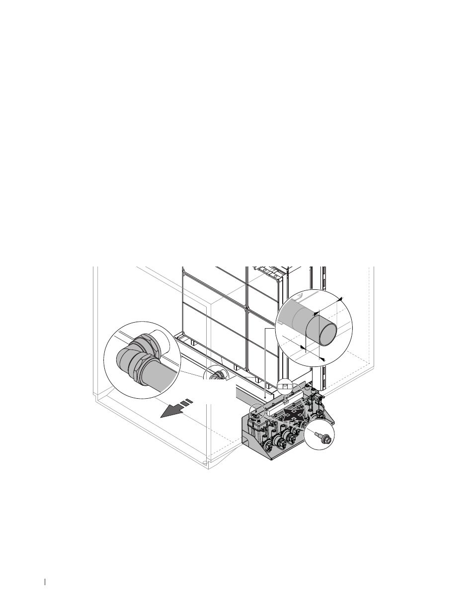
Fig. 16: Mount the hydraulic module of ME Circulating System (external installation)
46 mm
1.8
"
54 mm
2.1
"
constant
downslope
1 to max. 2%