Nortec ME Control Installation User Manual
Page 38
38 Installation
X16
JP5: 10V JP4: 24V
24/10V
TMP
GND
HUM
24V E
Enable
Y
B7
TEMP
–
24 V
T
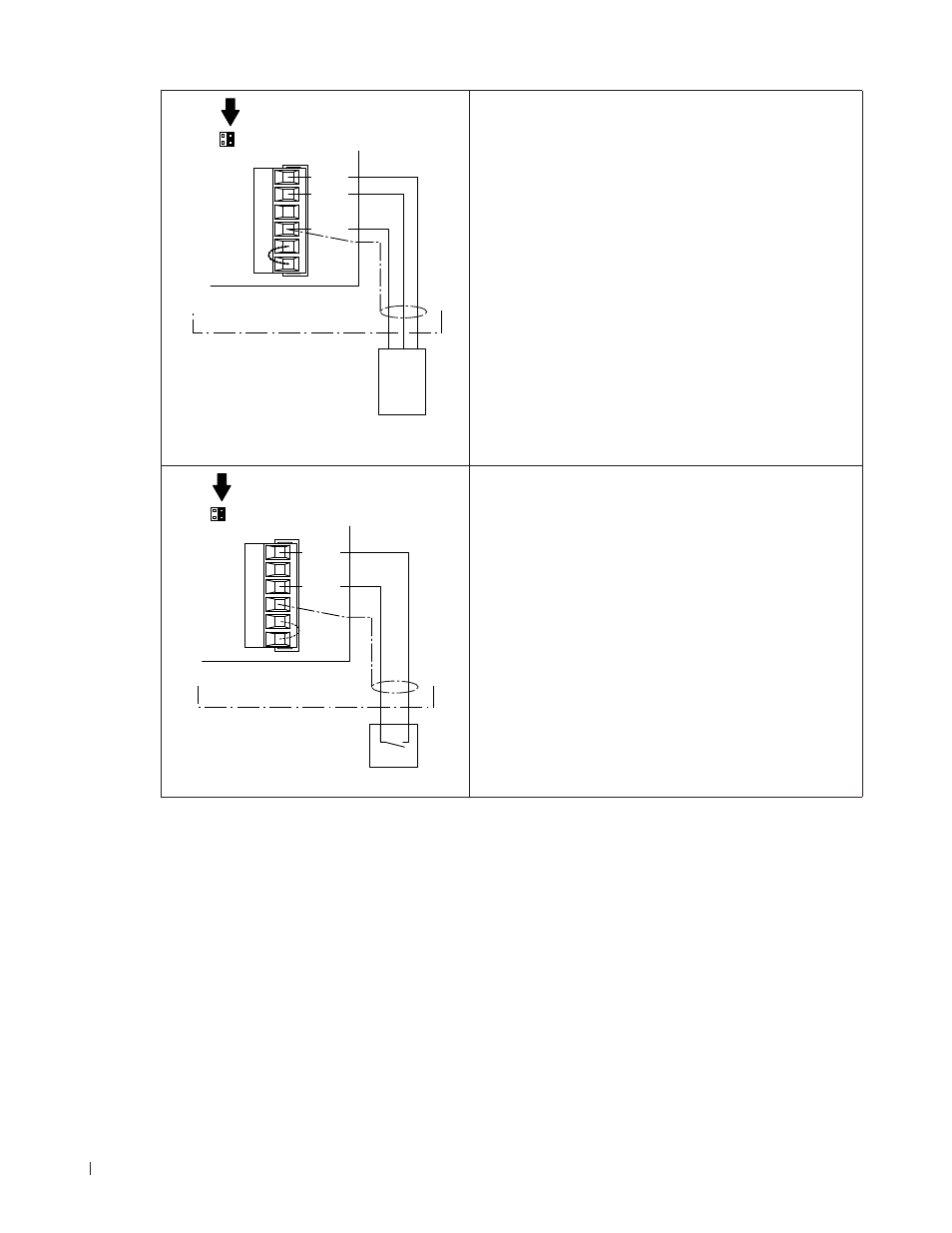
24 V - voltage supply
Control unit
Temperature sensor
A temperature sensor is to be connected to the contacts
“TMP” (+) and “GND” (–) of the terminal block “X16” on
the driver board. The admissible signal values can be
found in the technical data table in the operation manual.
The connecting cable must either be fed through the
rectangular cable feed through or a free cable gland
into the control unit.
Note: If 24V supply is used for the external controller
Jumper “JP4: 24V” must be set and Jumper “JP5: 10V”
must be removed.
The shielding of the control signal must be connected
to terminal “GND”.
Caution! If the shielding of the control signal is already
connected to a po ten tial or a grounded conductor,
do not connect it to terminal “GND”.
X16
JP5: 10V JP4: 24V
24/10V
TMP
GND
HUM
24V E
Enable
B7
ON/Off
Control unit
24 VDC On/Off humidistat
A 24 VDC On/Off humidistat is to be connected to the
contacts “24V” and “HUM” of the terminal block “X16”
on the driver board. The connecting cable must either
be fed through the rectangular cable feed through or a
free cable gland into the control unit.
Note: for the 24 VDC On/Off control jumper “JP5: 10V”
must be removed and Jumper “JP4: 24V” must be set.
The shielding of the control signal must be connected
to terminal “GND”.
Caution! If the shielding of the control signal is already
connected to a po ten tial or a grounded conductor,
do not connect it to terminal “GND”.