2 water installation (internal installation) – Nortec ME Control Installation User Manual
Page 29
29
Installation
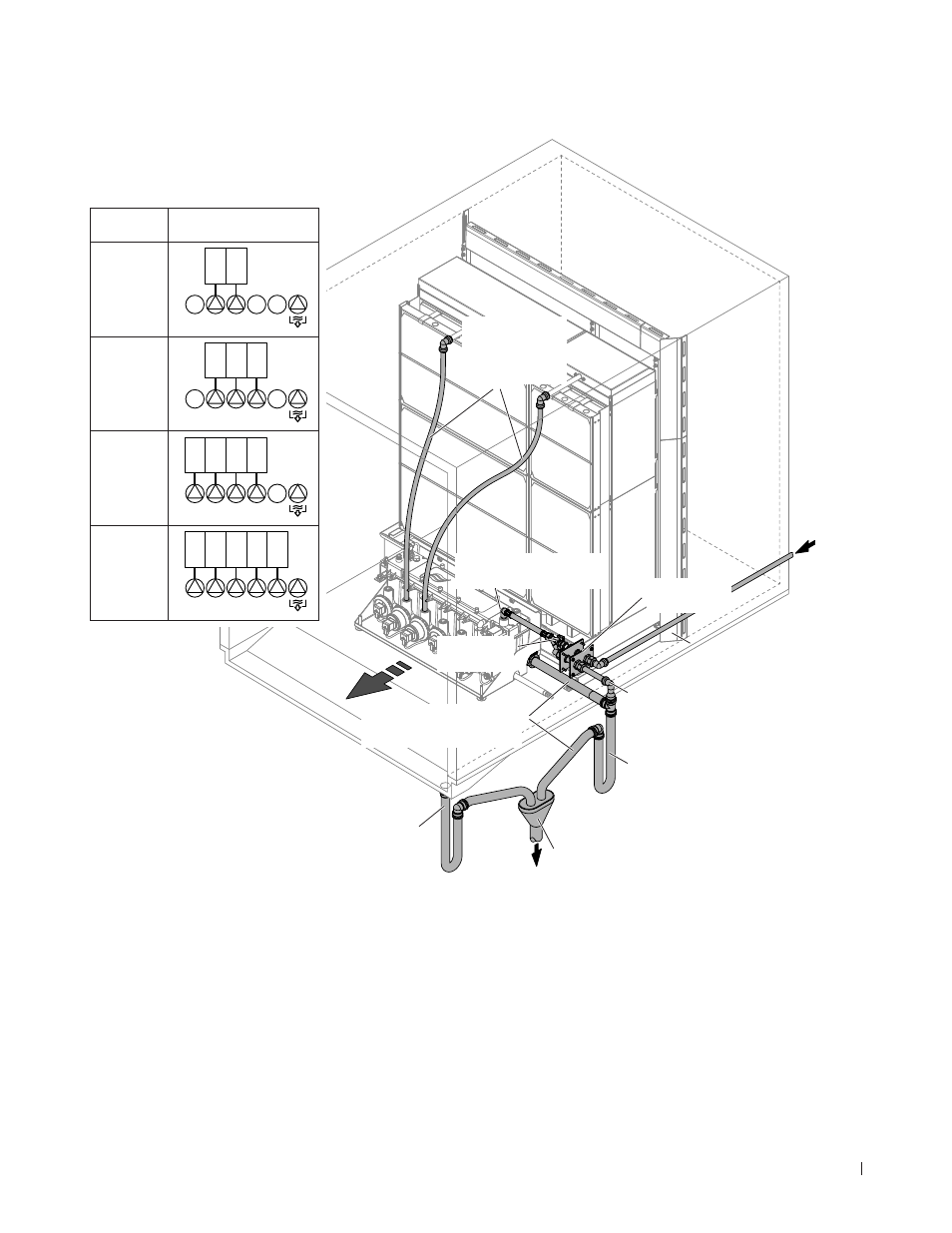
4.4.2 Water installation (internal installation)
Stages
(box rows)
Connection layout
distribution hoses
2
2 1
4 2 1 3 5
3
2 1 3
4 2 1 3 5
4
4 2 1 3
4 2 1 3 5
5
4 2 1 3 5
4 2 1 3 5
Distribution hoses
ø15 mm (0.625")
constant slope
(no sagging)
Water supply push-fit
connector ø15 mm (0.625")
Feed throughs
(supplied)
Drain pipe ø28 mm (1.125")
with constant downslope
1...2 % (not supplied)
Shut-off valve
(supplied)
Drain trap (not supplied)
Drain trap height: Allow a height of 25 mm
(1") for every 250 Pa of duct pressure (e.g.
100 mm (4") for 1000 Pa duct pressure)
Drain pipe vent (mandatory, not sup-
plied), highest point of vent tube must
be above max. water level of tank
Open tundish (not supplied)
AHU drain with drain trap (not supplied)
Drain trap height: Allow a height of 25 mm
(1") for every 250 Pa of duct pressure (e.g.
100 mm (4") for 1000 Pa duct pressure).
2...5 bar
Fig. 17: Water installation (internal installation)